SolidWorks Sample Assignment
Total Problems: 3 (350 points)
Create SolidWorks part files for problems 1 and 3, and part and drawing files for problem 2. You are required to submit four (4) SolidWorks files total, one (1) each for the first and third problem, and two (2) for the second problem.
General Instructions:
- All sketches must be fully defined, and no orphan entities may be present.
- All holes are through holes unless otherwise stated.
- All drawings must be ANSI Landscape, sheet size A, using an appropriate view scale.
- All ANSI Engineering Drawing conventions must be followed for the drawing files, including line placement/spacing/grouping.
- Drawings must be fully dimensioned, but need not be fully defined, as shown in lecture.
- Instructions colored in red must be followed, or the problem will receive zero (0) credit. No exceptions.
- A feature for the purposes of this assignment is any Feature Command that generates and/or modifies a volume present on the model (3D) space (e.g. Boss/Base, Cut, Hole Wizard, etc.).
- When creating subsequent boss/base features, make sure the box marked “Merge Result” is checked in the properties dialog.
- Be sure to follow 3rd angle projection method with appropriate orientation.
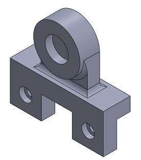
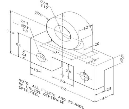
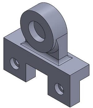
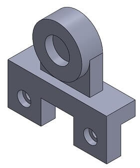
Problem 3: Make a SolidWorks Part file for the solid given in the figure below. All dimensions are in MMGS. The following parameters are given to aid in interpreting the figure below:
- The cylindrical feature on top is attached to the lower “L” bracket using a pedestal with a rectangular cross section.
Five (5) of the pedestal edges feature R6 fillets: one (1) each on the lower four (4) edges that intersect the bracket, and one (1) on the upper front edge that intersects the cylinder.
The pedestal's width and depth are given, the height is level with the cylinder's horizontal centerline, the rear surface is co-planar with the rear surface of the cylinder, and the position is symmetric with respect to the top surface of the bracket.
The three short horizontal hash marks at the top and bottom of the vertical centerline indicate the object is symmetric about that line in the front plane.
All sketches must be fully defined. (125 Points)
Solution
solidworks file:
Procedure:
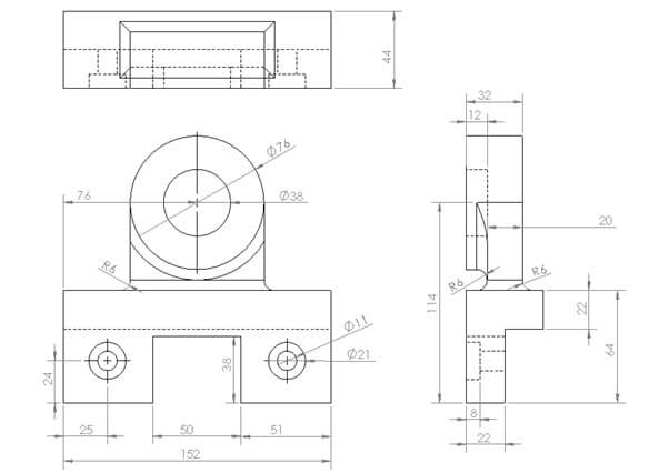
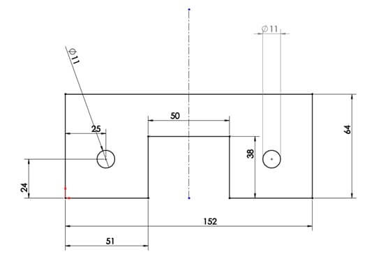
1.Create a new solidworks part file. Select front plane and sketch. First we create the L bracket. Draw the sketch as given in picture.
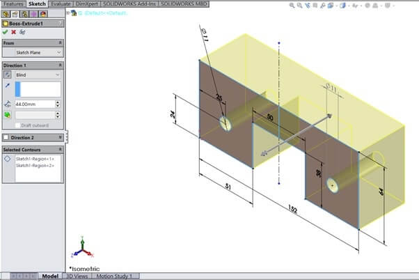
Select Boss Extrude
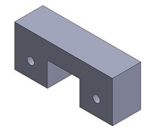
2.Select the right face of L Bracket and sketch. Draw the rectangle as per the diagram.
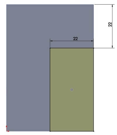
Select Cut-extrude and use through all in Direction 1.
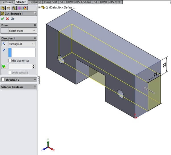
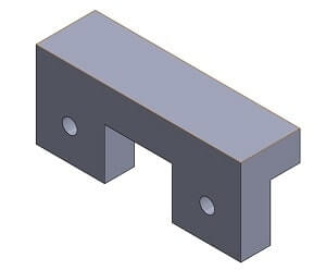
3.Select Front plane and sketch. Draw as per figure.
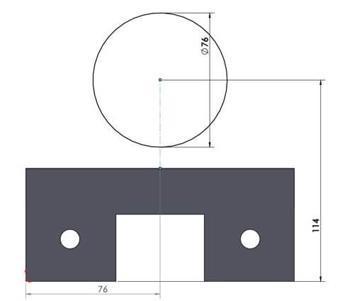
Use Boss Extrude ,Direction-1 as 32mm.
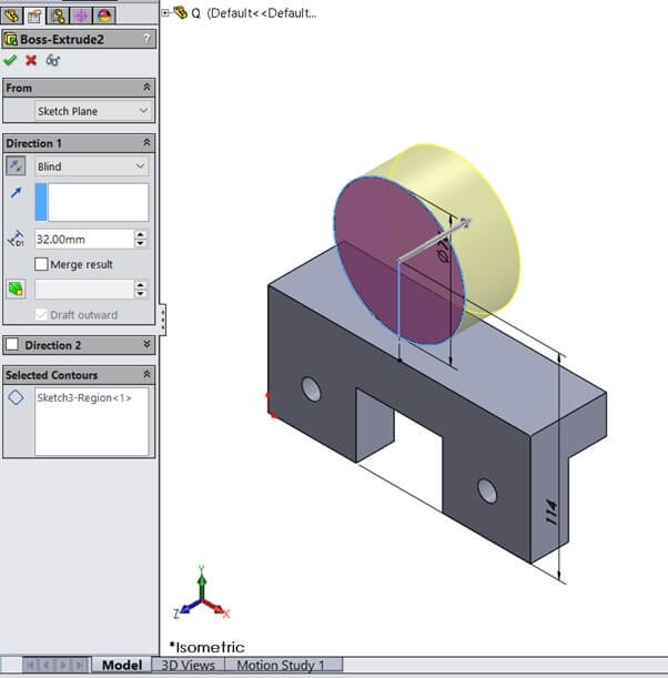
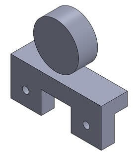
4.Select front plane and sketch. Draw as per figure.
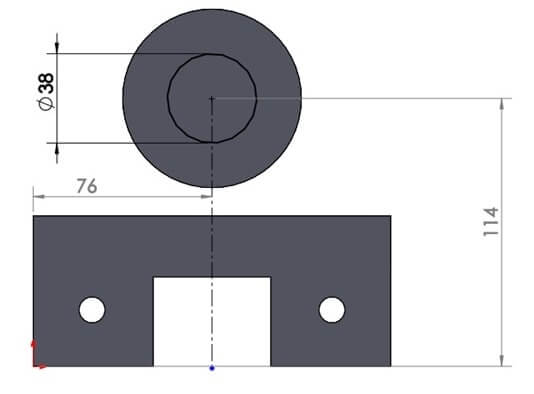
Select Cut-Extrude with direction-1 as 12mm.
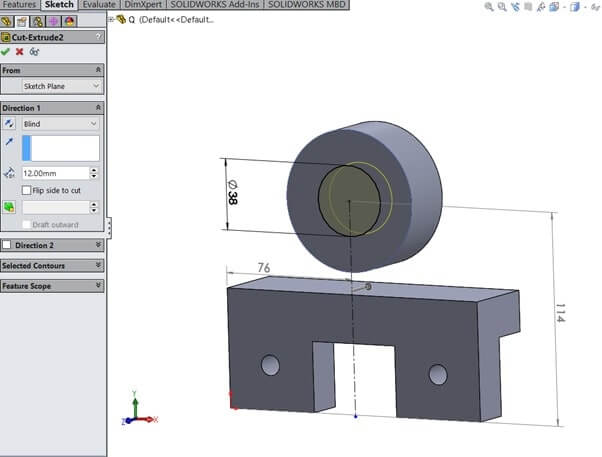
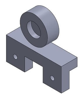
5.Select front-plane and sketch. As per figure.
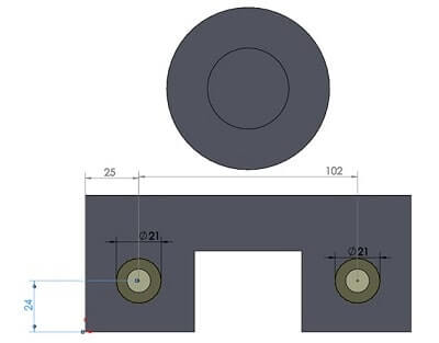
Select cut-extrude and direction-1 as 8mm.
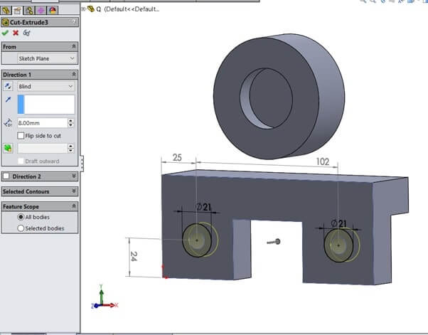
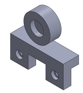
6.Select front plane and sketch.
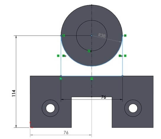
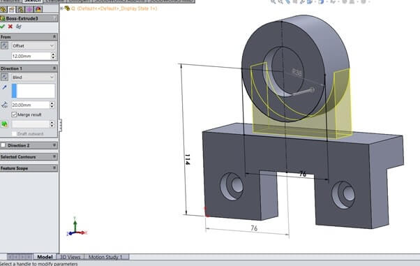
Select cut-extrude from as offset of 12mm and Direction-1 as 20mm.
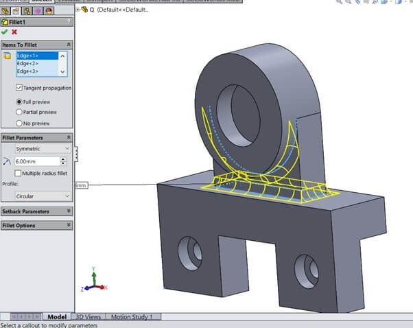
7.Select Feature->Fillet.Set parameters as 6mm and select edges 5 as given in question.
