Simulated engineering project
Introduction
This is a simulated engineering project for which you will have to carry out a finite element analysis on a single machine component. You will have to demonstrate your learning across the whole module, including the block materials, the ANSYS exercises and the case studies.
Although the component itself should be relatively easy to model, you will find that when it comes to meshing, applying the loads, deciding on boundary conditions, restraints etc., it is anything but simple. As is often the case, there is no ‘right answer’ – you will have to use your new-found analytical skills in making engineering judgements when tackling the analysis. You will also have to write up the project in a comprehensive report so that you can demonstrate these skills.
Remember that the examiners are looking for your understanding of the finite element analysis process. You will need to show that you are able to use FEA with safety and confidence, and that you can identify and justify assumptions and decisions made in your modelling, both implicit and explicit.
Make sure you leave yourself enough time for revising and developing your analysis models and to write up the report. Good luck!
1 The component to be modelled – a machine shaft
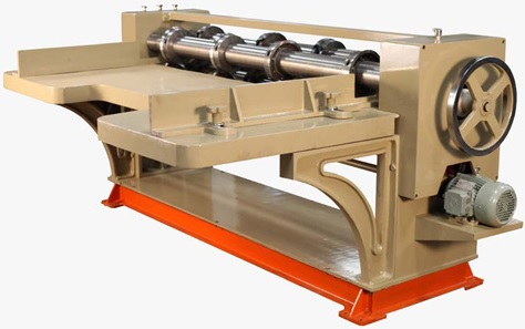
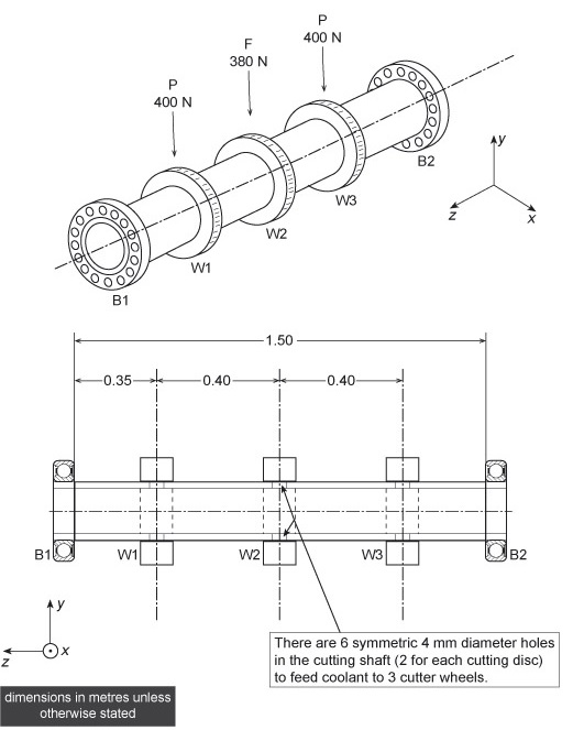
Figure 1 shows a typical roller cutting machine used in the mass production of insulating slab materials. The machine has several rotating parts including a cutting shaft. There are four rotating cutters fixed to the cutting shaft, of which only three cutters are used – see the sketches in Figure 2 for more details.

Figure 1 Roller cutting machine
A similar roller cutter design is to be studied for possible alternative applications in which the cutting loads will be somewhat higher. Hence, finite element analysis is being considered to determine the suitability of the existing shaft under higher loads and, if needed, to redesign it to fit the new purpose.
The cutting shaft has an annular cross section with an outer diameter of 80.0 mm, which cannot be changed, and an initial wall thickness, t, of 3.0 mm. The wall thickness can be changed but only in discrete steps of 1 mm. The shaft material is conventional structural steel, having a modulus of elasticity, E, of 206 GPa, a density of 7860 kg m–3 and a Poisson's ratio, ν, of 0.29.
The cutting shaft is located and supported by two roller bearings, B1 and B2, fitted at the ends, as shown in Figure 2. The bearings allow the shaft and cutters assembly to rotate at up to 2500 revolutions per minute about its longitudinal axis, which is parallel to the z direction, but prevent it moving radially (i.e. in the x–y plane).
The shaft is also restrained by circlip type retaining rings (not shown), which prevent it moving in the z direction but with sufficient play longitudinally to allow for any expansion and avoid hindering the rotation in all operating conditions. The bearings can be regarded as having infinite radial stiffness in comparison with the cutting shaft. However, since resistance to bending in the y–z plane (i.e. about an axis parallel to x) is unknown, fully constraint (encastré) and simple support conditions must be considered in both finite element analysis (FEA) modelling and theoretical (hand) calculations.

Figure 2 Simplified sketches of the cutting shaft (not to scale)
Two bearings (B1 & B2) and the three cutter wheels (W1, W2, W3) are positioned as shown in Figure 2. For this exercise, the cutter wheels themselves can be considered to have zero mass and can be neglected in terms of the effect on modelling the shaft. In the cutting shaft at each wheel position, however, are two holes diametrically opposed and each of 4 mm diameter, which feed coolant from the centre of the shaft to each cutter.
2 The analysis tasks – stress and modal analyses
In one loading condition the wheels are to sustain the radial loads shown in Figure 2 for short periods in operation. These have been ‘factored up’ to represent a worst-case design condition.
You are required to perform a stress analysis of the shaft for this loading condition, modifying its thickness (i.e. the only design variable) and re-analysing it as necessary to meet the design limit criteria stated below. You are also required to perform a normal mode vibration analysis of your chosen shaft design.
For the stress analysis it would be reasonable to neglect the masses of the shaft itself, the wheels and the bearings. It would also be reasonable to neglect the interaction between the cutting wheels and the shaft.
Hint: Given the uncertainty associated with resistance to bending, consider two extreme conditions in your analysis, i.e. simple supports and encastré (constrained) supports. The same assumptions and issues will apply for the modal analyses, except that the mass of the shaft should be taken into consideration.
Design Limit Criteria: It is required to limit the maximum deflection to 0.5 mm in order to maintain wheel alignments, and keep maximum tensile stresses below 60.0 MPa. You therefore have to choose a recommended dimension of minimum thickness to meet the criteria, and then carry out detailed analyses of your design with this thickness.
You have to submit a detailed report on your project analysis. We expect to see details of all the assumptions you make, your modelling strategy including selection of suitable element(s) for FEA, verification trials and details of validation processes, etc. You are advised to conduct many analyses, fine-tuning your model to provide valid modelling of important details, such as any stress raisers, until you are satisfied that the results are meaningful.
Your report should include the following:
- a clear statement of the problem and your approach to it;
- what FEA element(s) and mesh size(s) you chose and why;
- what boundary conditions you considered and decided upon, including how the loads are applied and the representation of any restraints;
- whether or not any symmetry or anti-symmetry conditions were applicable, and if so what additional boundary conditions you specified for these;
- what mathematical or other theoretical calculations you employed to validate the results;
- a discussion on whether or not using a high strength steel (with a higher yield strength but a similar modulus of elasticity) would affect the deflection and minimum thickness of the cutting shaft – no calculations or simulations are required;
- an appraisal of and comments on the results themselves in terms of the operation of the shaft and machine.
3 The main objectives
In summary, the objectives are:
- to determine the deflections and stresses sustained by the shaft in its operating conditions, including the magnitudes and locations of the maximum stress values
- to determine the first four normal modes of natural vibration of the shaft in the absence of loadings (i.e. free spinning)
- to discuss the effect of using a steel with higher yield strength on the deflection and minimum thickness of the cutting shaft
- to prepare a full report of the analysis strategy, the results and their implications.
4 The report
4.1 Format
Note that there are 28 study hours allocated, including the preparation of the report. We therefore expect a report, up to 20 A4 sides in length, plus any appendices for results and log files, plots of stresses, deflections, mode shapes, etc. (It is not necessary to include all of these – just those related to and illustrating your discussion in the main text of the report.)
There are restrictions on the size and format of any files you submit for the via the online service. The maximum file size permitted is 10 MB. You can only submit .doc, .docx, .xls, .xlsx or .rtf documents, or zipped files containing only .doc, .docx, .xls, .xlsx or .rtf documents.
4.2 Structure
You are free to adopt any style for writing your report but be advised that the allocation/availability of marks will be grouped as:
- 10% for the report presentation quality (including spelling, grammar, legibility and formatting)
- 60% for the stress and deflection analysis, including discussion on the effect of using a high strength steel:
- 30% for the normal mode analysis:
|
4% |
For correct assumptions and considering the stress concentration due to the holes. |
|
10% |
For clear reference to and implementation of the boundary conditions in each case. |
|
10% |
For selection and use of suitable FE model. |
|
6% |
For correct discussion and use of appropriate mesh size. |
|
4% |
For correct use of symmetry. |
|
6% |
For full and correct mathematical hand calculations. |
|
10% |
For comments and discussion of FEA results. |
|
10% |
For effects of using a high strength steel. |
|
10% |
For correct assumptions and selection of a suitable FE model and mesh size. |
|
5% |
For use of correct boundary conditions. |
|
5% |
For correct mathematical hand calculations. |
|
10% |
For cross-checking numerical values against mathematical hand calculations. And final discussion on modal behaviour of the shaft. |
The general format of your report could be as follows:
Title page with your name, personal identifier and a statement such as:
“This document has been prepared by ___and represents his/her own work.”
Executive summary
This should summarise the main aims of the analysis and its conclusions in no more than one page.
Notation
A list of symbols and/or explanation of terminology used.
Contents
A detailed list of all sections and sub-sections with page numbers.
Introduction
Introduces the problem and sets out aims and objectives and perhaps some background. Also perhaps gives your approach to the analysis.
Analysis
This is the main body of the report which should include descriptions of the modelling process, selection of element types, meshing, refinements, model limitations, etc.
Also, importantly, you should include the assumptions you have made or invoked, material properties, boundary conditions tried and specified, loading conditions, etc.
Effectively there will be two parts here covering:
- the stress and deflection analysis
- the normal modal analysis.
For both there should be serious attempts at verification calculations (i.e. mathematical hand calculations) and comments on the validity of your models and results obtained.
Discussion
You should have a detailed discussion section on your approach to the tasks, any problems or issues you may have encountered and the significance of the results and their validity, and what they may mean in the context of the machine operation.
Conclusions
This should be a section to confirm that you have done all you set out to do and all that the project brief requires, and possibly recommendations for further work if you had the time and resources.
References
Any references should be at the end of the main written sections followed by any acknowledgements and then by any relevant appendices which may contain details of log files, tables of results, stress plots, mode shapes, etc.


