Simple routing protocol project
PROJECT DESCRIPTION
1. OBJECTIVE
At the core of every link-state protocol is a distributed, replicated database. The database describes the routing topology -- the collection of routers in the routing domain and how they are interconnected. Each router in the routing domain is responsible for describing its local routing topology (e.g., status of its direct links, the cost associated with each link ...) to all other routers. The local routing topology information is reliably distributed to all other routers in Link State Advertisements (LSAs). Taken together, the collection of LSAs generated by all the routers form the Link State Database (LSD). Using the information contained in the database, each router builds a map of the current network topology. Armed with this map, each router uses a shortest path routing algorithm, typically Dijkstra's Shortest Path First, to calculate its routing table, thereby enabling forwarding of network traffic between end systems. The purpose of the project is to design and implement a simpleLink-State Routing Protocol (sLSRP). The protocol has the following main components:
- Support for a user interface for router configuration,
- Support for neighbor acquisition,
- Support for “Alive” messages,
- Support for periodic exchange of LSAs, and
- Computation of a routing table using Dijkstra's SPF algorithm, based on link metrics.
In the following sections, the main messages and basic functionality of sLSRP are describe.
2. sLSRP MESSAGES
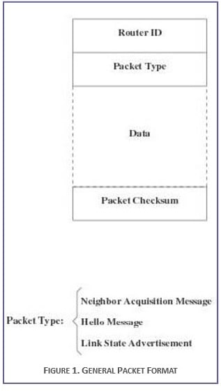
In order to accommodate sLSRP functionalities, the protocol defines three types of messages, namely “Neighbor Acquisition” messages, “Alive” messages, “Link Cost” messages, and “LSA” messages. The general format of sLSRP message is depicted in Figure 1.
2.1 Neighbor Acquisition Messages
The neighbor acquisition messages are used by two adjacent routers to establish “neighborhood” relationship for routing information exchange. This class of messages include “Be_Neighbors_Request”, “Be_Neighbors_Confirm”, “Be_Neighbors_Refuse”, “Cease_Neighbors_Request”, and “Cease_Neighbors_Confirm”.
The Be_Neighbors_Request message is used by one router to invite another router to become neighbors. In addition to the standard fields, the message contains initial values for the Hello_Interval, the Update_Interval, Router_ID, and any other parameter you see fit in the initialization process. The value of the Hello_Interval determines the amount of time a router waits before it tests if the neighbor is still alive. The Update_Interval determines the maximum frequency of the local link state updates. Additional parameters may include maximum packet length, if required, cost metrics, encryption keys, etc.
Upon receiving a Be_Neighbors_Request message, the invited router can either accept the invitation, in which case it replies by sending a Be_Neighbors_Confirm message, or reject the invitation by issuing a Be_Neighbors_Refuse message. The choice of accepting or rejecting a neighborhood request is made by the system administrator, and included in a policy management file. The router accepts or refuses neighborhood requests based on the content of the policy management file. The neighborhood decision is initially made during the router configuration phase, but can be modified any time thereafter. A router may also refuse an invitation to become a neighbor if it does not run the same version of the LSRP protocol as the requesting router’s version. In case of acceptance, the values of the initial parameters that govern the communication and LSA packet exchange between the routers are negotiated during this phase to accommodate the profile and capability of each router.

2.2 Alive Messages
The “Alive” messages are sent periodically by one router to test whether the neighbor is still alive. The period is determined by the value of the Hello_Interval parameter, agreed upon during negotiation.
2.3 Link Cost Messages
In order to estimate the link cost, the router uses a routine, typically implemented as a thread, to periodically measure the round-trip time to send a packet and receive an acknowledgement over a link to an adjacent router. The measurements over an Update_Interval are averaged out and mapped into relative cost, between 1 and Max_Cost, where high cost means heavily congested link and low cost means lightly congested link. How refined is the characterization of the link congestion is implementation dependent. The cost of links are then flooded to all routers in the networks, using a LSA message.
2.4 Link State Advertisement Messages
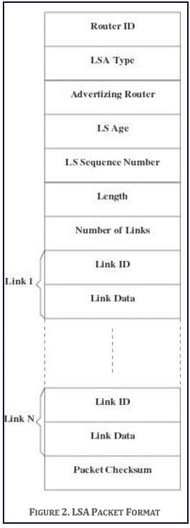
Each LSRP router originates one or more LSAs to describe its local part of the routing topology domain. The format of an LSA is depicted in Figure 2.
- Router ID: Identifies the router sending the LSA
- LSA Type: Classifies the packet as of type LSA Advertising Router. It identifies the originating router of the LSA. Knowing which router has originated a particular LSA tells the calculating router whether the LSA should be used in the routing calculation and, if so, how it should be used.
- LS Age: Indicates the number of seconds since the LSA was originated. This field is reset every time a new instance of the same LSA is received. If the age of the LSA reaches a predefined threshold, ‘‘Age_Limit’’, the LSA is deleted from the database.
- LS Sequence Number: This field is used by the routers to distinguish between instances of the same LSA. The LSA instance having the larger LS Sequence Number is considered to be more recent.
- Length: This field contains the length, in bytes, of the LSA counting both LSA header and contents.
- Number of Links: Identifies the number of links reported in the LSA.
- Link ID: Identifies the ID of the Link.
- Link Data: Contains all data describing the status of the link based on the routing metrics in terms of availability and cost. The cost metric, ranging from 1 to Max_Cost, indicates the relative cost of sending data packets over the link, namely the larger the cost, the less likely the data will be routed over the link.

Link state databases are exchanged between neighboring routers soon after the routers have discovered each other. After initial discovery, the link state database remains synchronized through a procedure called reliable flooding. The flooding procedure starts when a router wishes to update its self-originated LSA. This may be because it is time to refresh an LSA, based on Update_Interval, or because the router’s local state has changed. Changes may occur when one of the interfaces may have become nonoperational or one of the failed interfaces has become operational.
When a neighbor receives an LSA, the neighbor examines the LSA to verify that is not corrupted, checks that the LSA is more recent that the neighbor’s own database copy and installs the new LSA in its link state database. The neighbor then sends an acknowledgment to the sender and repackages the LSA within a new packet and sends out all interfaces, except the one that received the LSA in the first place. In order to achieve reliability, a sending router will periodically retransmit the LSA sent to a neighbor until the neighbor acknowledges the receipt of the LSA.
3. REQUIREMENTS
As a minimum requirement, sLSRP must:
- Provide a user interface that can be used to properly configure the protocol version number, update and alive intervals, the neighbor acquisition authorization, the link cost for each interface, and any other parameters as requested by your design. This is only done once at the beginning of the session.
- The user interface should allow viewing of the information contained in the transmitted and received routing table.
- The user interface should also allow the display of the shortest paths between routers.
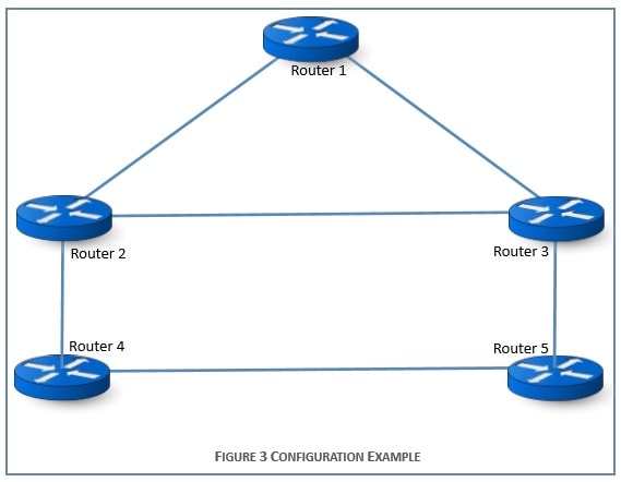
- Handle exchange of routing and control information in typical configurations such as the one depicted in Figure 3.
- Implement Dijkstra’s Shortest Path First algorithm to compute paths between routers. Linux sockets will be used to enable communications between adjacent routers.
- The implementation must handle packet errors and packet dropped due to congestion. To this end, you are to simulate packet error and packet dropping as follows:
- Packet Error Simulation: Prior to transmitting a packet, a router computes and appends the CRC to the packet. Furthermore, it generates a random number, 0≤ Pe ≤ 1. With probability Pe an error is introduced into the packet by altering at least one bit of the packet, before transmitting it to the neighboring router. Otherwise, the packet is transmitted with its original unmodified content. Errors will be detected by the receiving router, which then requests the retransmission of the packet.
- Network Congestion Simulation: Prior to transmitting a packet, either with or without an error, the router generates a random number, 0≤ Pc ≤ 1. With probability Pc the packet is dropped. Otherwise, the packet is transmitted to the receiving router. Dropped LSA packets may create inconsistencies in the LSA database and possibly induce a loop in the network topology. Your implementation should include mechanisms to handle database inconsistencies and loop formation.
- Using a simple file transfer application, demonstrate how data packets are routed correctly between the sender and the receiver.

4. PROJECT MILESTONES
The first milestone of the project deals with the design of the protocol architecture. Prior to implementing the system, you must submit an initial Design Report. The report should include the following:
- A detailed description of the structure of the user interface. The design of the interface should allow the user to ask and obtain at least one level of help for each command provided at the interface.
- A modular decomposition of each component of the system, a description of the interface between each pair of components, and a justification of your design choices. Careful thought must be given to the design to allow for new functionalities to be added to the system.
The proposed design and architecture report will be evaluated and either approved or recommended for modifications. It is only after approval that the team can start the second phase of the project.
The second milestone of the project is concerned with the implementation of the approved protocol design and architecture. You need to implement all the features and operations of the protocol for full credit. In addition to making the implementation source code, header files and parameter files available in a directory accessible to the instructor and the TAs, you need to submit:
- A final report detailing your design and implementation. In this report, you are expected to discuss the program design and implementation in detail, and justify whatever design decisions you have made.
- A well-documented user manual, explaining in detail how to compile (Make files are highly desirable), and run the program. Any restrictions your design may have must be included in this document.
You will be required to schedule a session at the end of the term to demonstrate the functionalities of your protocol


