MECH 0016 finite element analysis
{`Module: Finite Element Analysis (MECH 0016)
Level : 3
Session: A & B
Middle East College
`}
Introduction
Gear is basically a toothed wheel. But, it is one of the most important machine elements in mechanical power transmission system. It has a wide range of applications starting from wrist watch to heavy industries due to its high degree of reliability and compactness (Karaveer et al., 2013). In this project, the students are required to conduct a comprehensive Finite Element Analysis using ANSYS software and submit a complete report in the final stage.
Gear Design
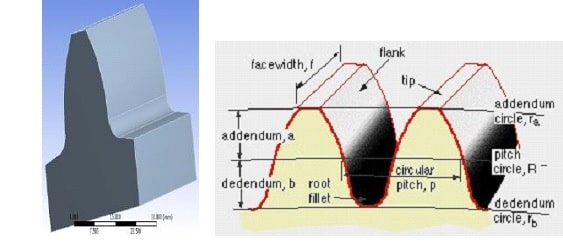
The general dimensions of the gear shown in Table 1 and the shape of the spur gear tooth is shown in Figure 1.
Table 1: Specification of spur gear tooth


Consider torque T = 132 N-m at 3000 rpm
The Tangential load can be obtain by 𝐹𝑡 = 2×𝑑𝑇 (1)
The theoretical bending stress is given by 𝜎𝑏 = (𝑚×𝐹𝑏𝑡×𝑌) (2)
Value of deflection is obtained by 𝛿= 16𝐸 𝑏𝐹𝑡 𝑡 ℎ33 (3)
Boundary Conditions
Based on the assumptions of Lewis equation, the boundary conditions are set in ANSYS model. The fixed support is used at the root end of the tooth and the force is applied on the face having components in Y and Z directions. The tangential force (Ft) having magnitude 1466.67 N has been introduced with component at Y and Z direction as 1378.2 N and 501.6 N respectively.
Points to be covered
In ANSYS software develop the spur gear tooth model, then, perform the following
- Generate the mesh and perform the mesh sensitivity analysis, then, show the optimum elements number.
- Conduct modal analysis and identify the first four modes (natural frequency) of the spur tooth.
- Conduct static analysis by applying the tangential force on the tooth face, then, determine the maximum Von Mises stress along with the maximum deformation.
- Conduct Transient analysis by assuming the load is not constant load (Assume any dynamic function to represent the transient load), then, plot transients Von Mises stresses and displacements.
- Compare the theoretical results obtained from Eq. (1) – (3) with the numerical results and identify the accuracy.
Reference
KARAVEER, V., MOGREKAR, A. & JOSEPH, T. P. R. 2013. Modeling and finite element analysis of spur gear. International Journal of Current Engineering and Technology, 3, 2104-2107.
Notes: Students are free to select any other mechanical components, however, they should reformulate the problem and write the report in a manner that cover the aforementioned points
Table 1: Mark distributions
|
Assignment Report (70%) | |
Task | Mark |
Introduction | 5 |
Model development | 10 |
Meshing process | 10 |
Modal Analysis | 10 |
Static Analysis | 10 |
Transient Analysis | 10 |
Results and Discussions | 10 |
Conclusion | 5 |
|
Assignment Simulation Saved File From ANSYS (30%) | |


