ENGR 3350 control systems
Design a controller for an electric vehicle using PID / PI controllers
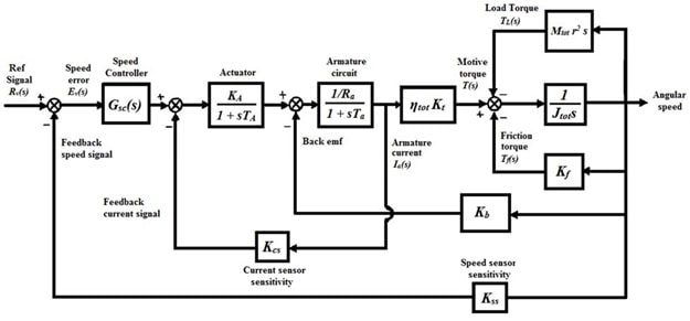
Electric motors are widely used in industries, such as traction motors installed in electric vehicles. In this project an electric vehicle, being propelled by a DC motor, is considered. The model of this electric vehicle is shown in the block diagram of Figure 1:

Figure 1: Block diagram of the electric vehicle powertrain
The driver applies the input Rv(s) to the vehicle by pushing the gas pedal. The block Gsc(s) represents the electric powertrain controller. The numerical values of all the parameters involved are tabulated below:
|
Parameter |
Value |
Parameter |
Value | ||
|
Wheel radius |
r |
0.25 |
Armature gain constant |
Ra |
1 |
|
Vehicle mass |
Mtot |
950 |
Armature time constant |
Ta |
5 |
|
Total inertia moment |
Jtot |
8.6 |
Actuator gain constant |
KA |
10 |
|
Friction torque gain |
Kf |
0.1 |
Actuator time constant |
TA |
5 |
|
Armature gain |
Kt |
2 |
Back emf gain |
Kb |
0.1 |
|
Efficiency |
ηtot |
0.9 |
In order to design a fast and reliable control system for the attitude control, the following tasks should be performed:
- Find the closed-loop transfer function without the controller, i.e., Gsc(s) =1.
- Perform the stability analysis of the closed-loop system by using the Routh-Hurwitz stability criterion. In order to achieve a stable system, what would be the relation between the current sensitivity gain, Kcs and the speed sensitivity gain Kss ?
- For the value of Kcs = 0.087, determine the gain Kss such that the system has a steady-state error of 2% for the unit-step input.
- Plot the root locus of the two systems and discuss about the stability of the system from the plots. Also, for the case of marginal stability determine the system gain.
- Plot the unit-step response of the system and find the attributes of the response.
- Plot the Bode diagram of the system and find the Phase Margin (PM), Gain Margin (GM) and the Band Width (BW). Determine their corresponding frequencies.
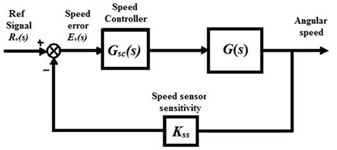
- According to Figure 1, find the transfer function G(s) of the plant:

Figure 2: The cascade controller Gsc(s)
- Select an appropriate controller for Gsc(s) as either PI or PID, and then design the controller to obtain Mp < 3% and ts < 35 seconds for the unit-step input. Explain your design procedure fully and justify your chosen controller type.
- Find the closed-loop transfer function of the compensated system. Determine the type of the system and calculate the steady-state error to an appropriate input.
- Plot the root locus of the compensated system. Discus the stability of the system.
- Plot the unit-step response of the compensated system. Find the attributes of the unit-step response and compare them with the uncompensated system.
- Plot the Bode diagram of the compensated system and determine the PM, GM and BW. Compare with the uncompensated system frequency response attributes.


