Drilling Engineering Exam Answers
{`HERIOT-WATT UNIVERSITY
INSTITUTE OF PETROLEUM ENGINEERING
MSC/DIPLOMA COURSE DEGREE EXAMINATION IN PETROLEUM ENGINEERING
DRILLING ENGINEERING
`}
SECTION A
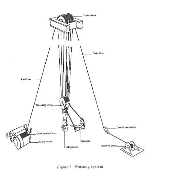
A 1 Draw and label a diagram of the component parts of the circulating system on a land drilling rig. [ 4]
A2 Calculate the tension on the fast line and the dead line and the vertical load on the derrick when the following drillstring is pulled from the well.
Buoyant weight of string      210,000 lbs
Weight of travelling Block and hook  8,000 lbs
Number of Lines strung between crown and travelling block 8
Efficiency of sheave system 81.4%
Load on Fastline: 210000+8000/8*0.814 = 33477lbs.
Load on Deadline: 210000+8000/8 = 27250lbs.
Load on Derrick: 33477 + 27250 + 210000 + 8000 = 278727lbs
A3 Describe three reasons for using Stabilisers in the drillstring
In vertical holes the functions of stabilisers may be summarised as follows:
- Reduce buckling and bending stresses on drill collars
- Allow higher WOB since the string remains concentric even in compression.
- Increase bit life by reducing wobble (i.e. all three cones loaded equally).
- Help to prevent wall sticking.
- Act as a key seat wiper when placed at top of collar string.
A4 Briefly describe the structure and content of the IADC dull grading system.
Eight coloms
Column 1 -Cutting Structure Inner Row (f): wear range 0-8
Column 2 -Cutting Structure Outer Row (O): wear range 0-8
Column 3-Cutting Structure Dull Characteristics (D): e.g BT- Broken Teeth
Column 4 -Cutting Structure Location (L) : nose, middle, gage or all rows
Column 5 -Bearing Condition (B): Effective of failed
Column 6 - Gauge (G) : level of wear an outside of bit
Column 7-Remarks (O): Other Dull character
Column 8-Reason for Pulling (R): e.g. ROP
AS List and discuss the major considerations when selecting/designing a drilling fluid for a particular well.
The primary functions of a drilling fluid are:
- Remove cuttings from the Wellbore
- Prevent Formation Fluids Flowing into the Wellbore
- Maintain Wellbore Stability
- Cool and Lubricate the Bit
- Transmit Hydraulic Horsepower to Bit
The drilling fluid must be selected and or designed so that the physical and chemical properties of the fluid allow these functions to be fulfilled. However, when selecting the fluid, consideration must also be given to:
- the environmental impact of using the fluid
- the cost of the fluid
- the impact of the fluid on production from the pay zone
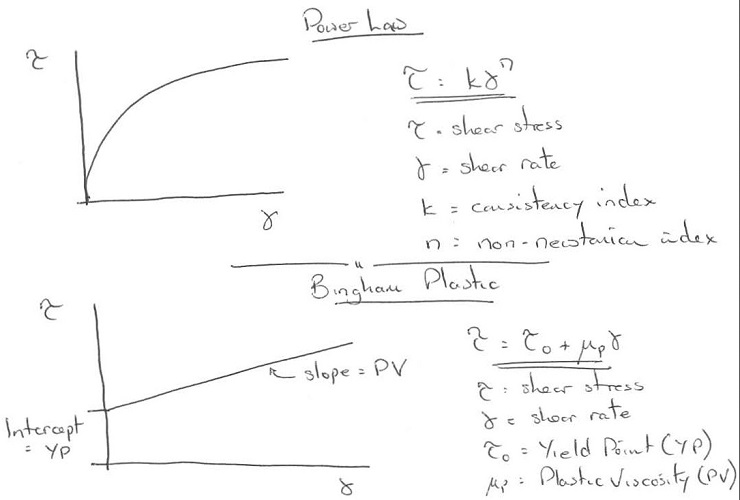
A6 Draw and label the shear stress vs. Shear rate diagram for a Power law and Bingham Plastic Drilling Fluid. Write the mathematical model for each of these models .
A 7 A typical casing string may be described by the following terms:
9 5/8" 4 7 lb/ft L-80 V AM
Explain the meaning of each of the terms in this description. Use examples of alternatives to hi ghlight the attributes of this particular casing
Casing Size (Outside Diameter-O.D.)
- outside diameter (O.D.)
- not the connector
- 4.5" to 36"
- less than 4.5" are called Tubing.
Casing Weight
- weight per foot of the casing indicates strength
- wall thickness- indicates strength
- strict tolerances on the dimensions of casing, set out by the API,
- actuaii.O. of the casing will vary slightly in the manufacturing process.
- drift diameter -guaranteed minimum 1.0. of the casing/deciding whether certain drilling or completion tools will be able to pass through the casing
- nominal/.D. of the casing is used for calculating the volumetric capacity of the casing.
Casing Grade
- classified by the API into a series of "grades".
- indication of the strength of the casing-higher the grade, the higher the strength
- The letter-chemical composit ion of the material and manufacturing process
- number-minimum yield strength of casing
Connections
API-threaded used for oilwells
- short thread connection (STC)
- long thread connection (LTC)
- buttress thread connection (BTC)
premium; gastight; and metal-to-metal seal.
- (e.g. Hydril, Vallourec, Mannesman).
- designed to contain high pressure gas
- specific surface machined into both the pin and box of the connection which are brought together and subjected to stress when the connection is made up.
SECTION B
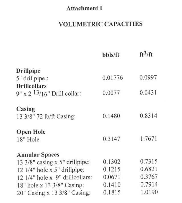
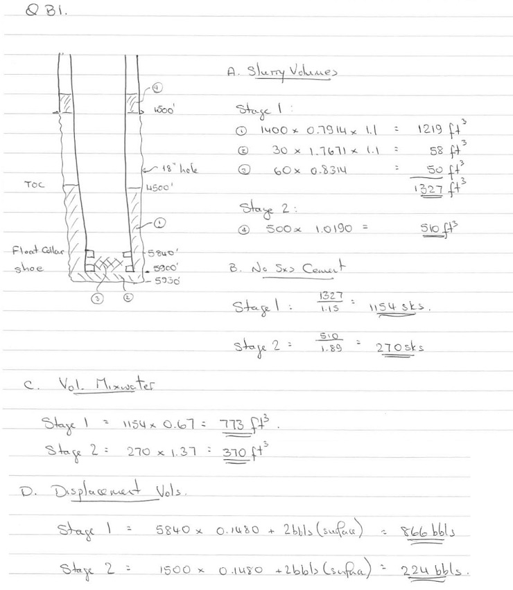
B 1 The intermediate casing of a development well is to be cemented in place using a two stage cement job.
13 3/8" Setting Depth  : 5900 ft
17 1/2" Hole (Calipered to 18") : 5930 ft
Previous Shoe Depth (20") : 1500 ft
Formation Fluid Density :9 ppg
Shoetrack : 60ft
Cement stage 1 (5930-4500 ft.)
Class ' G' + 0.2% D13R (retarder)  : 15.8ppg
Yield of Class 'G' + 0.2% D13R  :  1.15 ft3/sk
Mixwater Requirements   : 0.67 ft3/sk
Cement stage 2  ( 1500-1 000 ft.)
Class 'G' +  8% bentonite+ 0.1% D13R  :  13.2 ppg
Yield of Class 'G' +  8% bentonite+ 0.1% D13R :  1.89 ft3/ sk
Mixwater Requirements :  1.37 ft3/sk
(a) Calculate the following (See Attachment 1 for capacities):
(i) The required number of sacks of cement for the 1st stage and 2nd stage of the job (Allow l 0% excess over caliper in open hole).
(ii) The volume of mixwater required for each stage
(iii) The displacement volume for each stage
(b) List and discuss three properties of cement which would be specified when designing the cementation operation.
Cement Density-Ensure that influx does not occur when cementing or that formation will not fracture when cementing
thickening time-Ensure that there is time for mixing, pumping, displacing and for problems during the operation. Ensure that the cement does not take too long to set -to avoid woe.
Compressive Strength-ensure that the cement sheath is strong enough to create a competent seal and to sustain perforation tunnels if on the production string
(c) Write a program for a two stage cementing operation and describe the ways in which a good cement bond can be achieved
First stage
The first stage procedure can be summarised as follows:
I. circulate the casing and annulus clean with mud (one casing volume pumped)
2. pump spacer
3. pump cement
4. release shut-off plug
5. displace with displacing tluid (generally mud) until the shut-of'fplug lands on the tloat collar
6. Pressure test the casing and bleed off and check returns
Second stage
The normal procedure for the second stage of a two stage operation is as follows:
I. drop opening dart
2. pressure up to shear pins
3. circulate though stage collar whilst the first stage cement is setting
4. pump spacer
5. pump second stage slurry
6. release closing plug
7. displace plug and cement with mud
8. pressure up on plug to close ports in stage collar and pressure test the casing.
9. bleed off and check returns
Centralise casing
Move casing (ls1 Stage)
Pump as fast as possible to achieve turbulence in Spacer
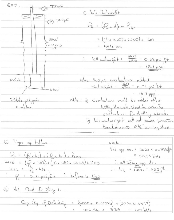
B2 Whilst drilling the 12 114" hole section of a vertical well with a mudweight of 11 ppg the driller detects a kick. The well is shut in and the following information is gathered
Surface Readings:
Shut in Drillpipe Pressure  : 700 psi
Shut in Annulus Pressure     :900 psi
Pit Gain                    :29 bbls
Hole I Drillstring Data :
Hole Size        : 121/4"
Depth of kick : 6500 ft
Previous Casing Shoe : 13 3/8", 54.5lb/ft
Depth 13 3/8" shoe : 3500 ft. TVD
LOT at Previous Shoe : 2975 psi (0.85 psi/ft Equiv. Mudweight)
BHA:
Bit  : 12 114"
Drillcollars :500 ft of 9" x 213/ l6"
Drill pipe : 5", 19.5 lb/ft
(a) Calculate and discuss the following :
(i) The type of fluid that has entered the well bore ?
(ii) The mudweight required to kill the well.
(iii) The volume of kill mud that would be required to reach the end of stage 1 of the well killing operation (assuming that the One Circulation kill method is used).
(b) Briefly explain how and why the well bore pressure is monitored and controlled throughout the well killing operation (assuming that the 'one circulation method' is to be used).
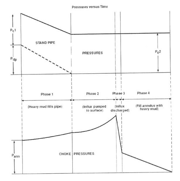
- Principal aim is to keep bottom hole pressure constant
- Kill mud is pumped at a slow and constant rate throughout operation
- Pressures in the well are controlled by operation of the choke on the annulus outlet
Phase I (displacing drillstring to heavier mud)
- pumping the kill mud down the drillstring the choke is opened.
- The choke should be adjusted to keep the standpipe pressure decreasing as shown on the worksheet.
- pressure is reduced in steps by maintaining standpipe pressure constant for a period of time, then opening it more to allow the pressure to drop in regular increments.
- Once the heavy mud completely fills the drillstring the standpipe pressure should become equal to Pc2·
- The pressure on the standpipe decreases due to the increase in hydrostatic pressure caused by the heavier killmud ..
- The pressure on the annulus usually increases due to a reduction in hydrostatic pressure caused by gas expansion in the annulus.
- Phase II (pumping heavy mud into the annulus until influx reaches the choke)
- choke is adjusted to keep the standpipe pressure constant (i.e. standpipe pressure =Pc2 for remainder of the operation
- The standpipe pressure remains constant assuming: the bottomhole pressure is constant; the hydrostatic pressure in the drillstring is not changing; the pumping rate is constant and the choke operator controls the choke correctly.
- annulus pressure will vary more significantly than in phase I due to 2 effects:
- (i) the increased hydrostatic head due to the heavy mud will tend to reduce Pann.
- (ii) if the influx is gas, the expansion will tend to increase Pann due to the decreased hydrostatic head in the annulus.
- The profile of annulus pressure during phase II therefore depends on the nature of the influx .
Phase ll l(time taken for all the influx to be removed from the annulus)
- hydrostatic pressure in the annulus will increase due to heavy kill mud being pumped through the bit to replace the influx.
- Pann will reduce significantly.
- If influx is gas this reduction may be very severe and cause vibrations which may damage the surface equipment (choke lines and choke manifold should be well secured).
- standpipe pressure should remain constant for same reason as in Phase II.
Phase IV (stage between all the influx being expelled and heavy mud reaching surface)
- the original mud is circulated out of the annulus replaced by a full column of heavy kill mud.
- annulus pressure will reduce to 0 due to hydrostatic pressure from the col om of kill mud in the annulus, and the choke should be fully open.
- The standpipe pressure should still be equal to P c2 for same reason as in Phase II.
- check that the well is finally dead the pumps can be stopped and the choke closed.
- The pressures on drillpipe and annulus should be 0 (if not continue circulating). When the well is dead open the annular preventer, circulate and condition the mud prior to resuming normal operations
(c) Briefly explain why the 'one circulation method' is considered to be safer than the drillers method for killing a well
The One Circ method is considered safer than the Drillers method because:
- The max. annulus pressure is less. Thus there is less risk of fracturing the formation at the casing shoe
- The wellhead is exposed to high pressure for less time
- It is easier to maintain a constant Pbh by adjusting the choke.
(d) List and briefly describe three of the warning signs that a driller should see if a gas influx had occurred downhole.
The primary indicators of a kick are as follows:
- Flow rate increase-flowrate into well should equal flowrate out of well. Increase in flow out indicates contribution to flow from influx.
- Pit volume increase - fixed volume of mud circulating so increase in pits indicates fluid entering well at bottom of well
- Flowing well with pumps shut off -formation pressure higher than borehole pressure therefore underbalanced and influx occurs and flow seen at surface
- Improper hole fill up during trips- indicates that fluid is entering well at bottom of the hole
The most common secondary indicators that an influx has occurred are:
- Drilling break-chip hold down reduces therefore higher ROP
- Gascut mud-increase in gas due to lower overbalance
- Changes in pump pressure-due to lower density/lower viscosity in annulus
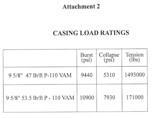
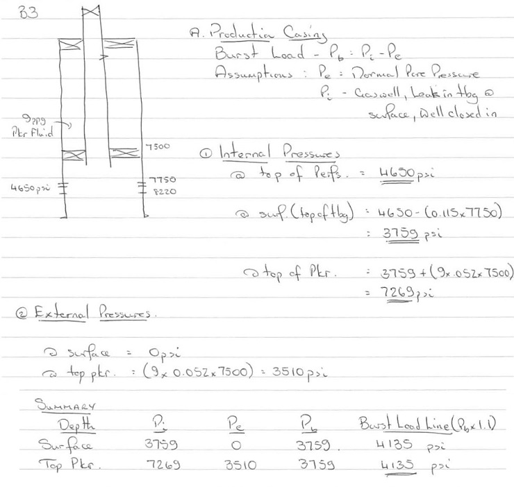
B3. The 9 5/8" production casing string of a well is to be designed for burst and collapse on the basis of the following data.
Setting Depth of9 5/8" Casing : 8320 ft
Top of Production Packer  :7500 ft
Normal Formation Fluid Density :9 ppg
Expected gas gradient : 0.115 psi/ft
Depth of Production Interval (TYD)  : 7750-8220 ft
Maximum expected pressure at top of Production interval  :4650 psi
Packer fluid density  :9 ppg
Design Factors (burst) : 1.1
(collapse)              : 1.1
Casing Available (See Attachment 2 for specifications of this casing):
9 5/8" 47 lb/ft P-110 YAM
9 5/8" 53.5 lb/ft P-110 YAM
Note : Only one weight and grade of casing is to be used in the string
(a) Design the casing for Burst and Collapse loads (do not consider the tensile loads). Discuss critically the scenario s considered when determining the loading conditions used in the above design process. [ 1 1]
(b) List and describe four (4) of the tensile loads which would be considered when designing the casing for tension.
Dry weight of Casing
The suspension of a string of casing in a vertical or deviated well will result in an axial load.
Buoyant Force on Casing
When submerged in a liquid the casing will be subjected to a compressive axial load. This is generally termed the buoyant force
Bending Stress
When designing a casing string in a deviated well the bending stresses must be considered. In sections of the hole where there are severe dog-legs (sharp bends) the bending stresses should be checked. The most critical sections are where dog-leg severity exceeds lOoper 100'.
Plug Bumping Pressure
The casing will experience an axial load when the cement plug bumps during the cementation operation.
Overpull when casing stuck
If the casing becomes stuck when being run in hole it may be necessary to apply an overpull' on the casing to get it free.
Effects of Changes in Temperature
When the well has started to produce the casing will be subjected to an increase in temperature and will therefore expand. Since the casing is restrained at surface in the wellhead and at depth by the hardened cement it will experience a compressive( buckling) load.
Overpull to Overcome Buckling Forces
When the well has started to produce the casing will be subjected to compressive (buckling) loads due to the inc rease in temperature and therefore expansion of the casing. Attempts are often made t o compensate for these buckling loads by applying an overpull to t he casing when t he cement i n the annulus has hardened. This tensile load (t he overpull) is ' locked into' the string by using the slip type hanger
Axial Force Due to Ballooning (During Pressure Testing)
If the casing is subjected to a pressure test it will tend to 'balloon'. Since the casing is restrained at surface in the wellhead and at depth by the hardened cement, this ballooning will result in an axial load on the casing.
Effect of Shock Loading
Whenever the casing is accelerated or decelerated, being run in hole, it will experience a shock loading. This acceleration and deceleration occurs when setting or unsetting the casing slips or at the end of the stroke when the casing is being reciprocated during cementing operations.
(c) List and discuss the operations involved in running casing, from the point at which it arrives on the rig, to the point at which the cementing operation is about to commence.
Handling Procedures
- do not stack the casing too high or else excessive lateral loads will be imposed on the lowermost row.
- Casing is off-loaded from the supply boat in reverse order, so that it is stacked in the correct running order
- The length, grade, weight and connection of each joint should be checked
- each joint should be clearly numbered with paint.
- The length of each joint of casing is recorded on a t ally sheet .
- If any joint is found to have damaged threads it can be crossed off the tally sheet.
- The tally sheet is used by the Drilling engineer to select those joints that must be run so that the casing shoe ends up at the correct depth when the casing hanger is landed in the wellhead.
- While the casing is on the racks the threads and couplings should be thoroughly checked and cleaned. any loose couplings should be tightened
- Casing should always be handled with thread protectors in place. These need not be removed until the joint is ready to be stabbed into the string.
Casing Running Procedures
- Before the casing is run, a check trip should be made to ensure that there are no tight spots or ledges which may obstruct the casing and prevent it reaching bottom
- The drift 1.0. of each joint should be checked before it is run.
- Joints are picked up from the catwalk and temporarily rested on the ramp. Asingle joint elevator is used to lift the joint up through the "V" door into the derrick (Figure 10).
- service company (casing crew) is usually hired to provide a stabber and one or two floormen to operate the power tongs. o The stabbing board is positioned at the correct height to allow the stabber to centralise the joint directly above the box of the joint suspended in the rotary table.
- The pin is then carefully stabbed into the box and the power tongs are used to make up the connection slowly to ensure that the threads of the casing are not cross threaded.
- Care should be taken to use the correct thread compound to give a good seal. o The correct torque is also important and can be monitored from a torque gauge on the power tongs.
- On buttress casing there is a triangle stamped on the pin end as a reference mark. The coupling should be made up to the base of the triangle to indicate the correct make-up.
- as more joints are added to the string the increased weight may require the use of heavy duty slips (spider) and elevators .
- If the casing is run too quickly into the hole, surge pressures may be generated below the casing in the open hole, increasing the risk of formation fracture. Arunning speed of 1000 ft per hour is often used in open hole sections. If the casing is run with a float shoe the casing should be filled up regularly as it is run, or the casing will become buoyant and may even collapse, under the pressure from the mud in the hole.
- The casing shoe is usually set 10-30 ft off bottom.
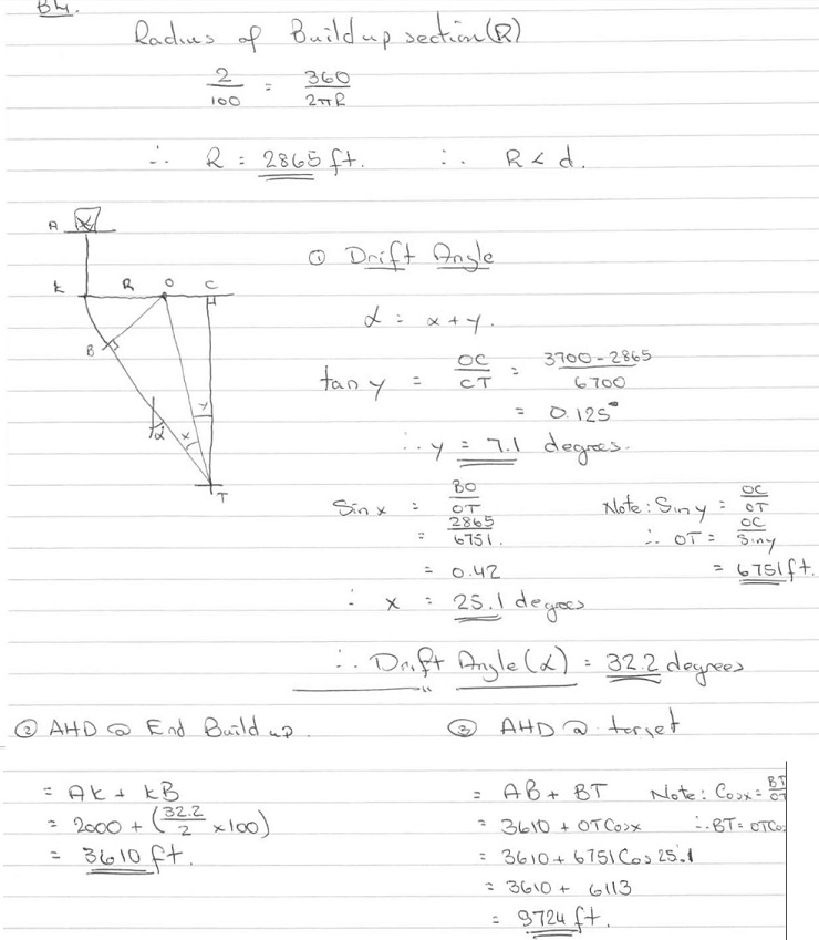
B4. It has been decided to drill a deviated well to a target at 8700 ft. TVD. The well is to be kicked off just below the 13 3/8" casing at 2000 ft. The well is to have a build and hold profile. The details of the well profile are as follows
KOP : 2000ft
Target Depth (TVD) : 8700ft
Horizontal Departure of Target :3700 ft
Buildup Rate : 2011 OOft
a) Calculate the Following :
(i) The drift angle of the well.
(ii) The along hole depth at the end of the build up section.
(iii) The along hole depth at the target
(b) List and discuss the advantages and disadvantages of the various types of surveying systems that could be used to survey this well whilst drilling.
Magnetic Single Shot (MSS)
- Robust and simple device
- Takes time to trip into and out of hole-costing rig time
- Subject to interference from magnetized equipment in drillstring and casing-have to use non magnetic drillcollars
- Have to correct for magnetic declination Possible errors reading from photographic disc
Gyro single Shot
- Not as robust and simple device as the MSS
- Requires specialist operators to run
- Takes time to trip into and out of hole-costing rig time
- Not subject to interference from magnetized equipment in drillstring and casing
MWD
- "real time" measurements transmitted to surface
- o no need to run and pull tool to make survey, saving rig time
- o frequency of surveys improves accuracy of determining position
- Robust device
- Requires specialist operators to run
- Expensive if lost in hole
(c) List and discuss two types of tool or techniques that could be used to alter the direction of this well if it were found to be deviating from the designed course.
Bent Sub and Mud motor
- Has to be tripped when drilling tangent section
- Cheaper than other systems
- Hole cleaning poor when drilling build sections
Conventional Steerable Drilling System
- Doesn't have to be tripped when drilling tangent sections
- More complex than Bent sub and mud motor
- More expensive than BS and MM
- Hole cleaning poor when drilling build sections
(d) List and discuss the issues which must be considered when designing the tangent section of a deviated well
Tangent (or Drift) Angle
This section of the well is termed the tangent section because it forms a tangent to the arc formed by the build up section of the well. The tangent angle will generally be between 10 and 60 degrees since it is difficult to control the trajectory of the well at angles below 10 degrees and it is difficult to run wireline tools into wells at angles of greater than 60 degrees. It is also difficult to remove the cuttings from the well and high torque and drag can be experienced on the drillstring