CMPE462 computer interfacing
{`Qatar University
College of Engineering
Department of Computer Science & Engineering
Lab. Section
`}
Lab#10: Design#2 (10%)
1$ Color Sensor with LDR
Design Requirements
Design a color sensor using RGB LED & a Light Dependent Resistor (LDR). On the Front Panel, add a color indicator to display the detected color. On the following pages, you can find some useful information.
An example can be found here: https://iamzxlee.wordpress.com/2014/03/05/colour-sensor
Report Requirements
- Introduction:
- Describe the design of the sensor. It should include a clear drawing (ok by hand) and several close & clear photos (of the sensor only).
- Tables of calibration data
- Concept of the VI. Put an image of the Block Diagram. Show clearly all labels. If using multiple cases, put a copy for each case. Below each image, put a clear description.
- Put several images of the Front Panel when the VI is operational.
- Connection Diagram. Use MultiSim or any other similar tools. All labels must be visible and clear.
- Put a photo (top view) of the hardware.
- Discussion: What was difficult in this design? What is the percentage efficiency of the sensor?
Resources
Color theory
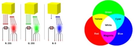
Color perception performed by the electronic circuit is based in color theory concepts. Since there are no lenses involved, only objects with opaque (and matte) material should be considered, avoiding to deal with specular reflection of the LED. Diffuse reflection on the other hand is the key to perform color detection with lights. From an incident light, it is reflected in irregular surfaces, not creating that glowish effect that ruins the function of the LDR Cell.
Back to actual color theory, when light (of a certain color) reaches an object, it is reflected according to properties of that object’s color. For example, a red light reaching a yellow object will be reflected according to how much red exists in the composition of that yellow color - remember, we are talking about lights! - So it is expected to have a lot of red light being reflected, what makes sense when we think of the RGB composition of yellow (essentially red and green). However, when a blue light reaches the yellow object, no strong reflection is expected due to low presence of blue in the color composition.

Considering an additive color system, in which white and black are respectively presence and absence of every colors, there can be measured (with the LDR Cell) maximum and minimum reflections of each light from the RGB LED which will reach colored objects. That said, it is possible to perform the calibration in electronic components involved in the circuit. This is another key to get fidelity in detection, as well as to ensure a stable detection of patterns (avoiding outliers) - here is a golden tip: after calibrating, try (hard!) not to move or touch neither the electronic components (especially when they are placed in a breadboard), nor the piece you are using (you must use) to isolate components from ambient light.
Reference: http://www.moretticb.com/blog/color-sensor-prototype-using-neural-networks/
Calibration
http://www.moretticb.com/blog/color-sensor-prototype-using-neural-networks/
For calibration and recognition, the color sensor executes three iterations on each color. In the first iteration, red light hits the object and the program waits LDR cell to stabilize its sensing; the analog input is then read and the reflection of the red light is stored. The program iterates twice more for green and blue colors.
On each iterative process, measure the voltage coming from the LDR. Fill the table. Repeat the measurements several times:
|
Color |
LDR Voltage | ||||||
|
White | |||||||
|
Red | |||||||
|
Green | |||||||
|
Blue | |||||||
|
Black | |||||||
Concerning calibration, the iterative process mentioned above is performed twice: once for black color and once for white color. This is for obtaining a true range to properly rescale to intervals.
Read this >> LDR + RGB Led = Color sensor. How to calibrate it? http://electronics.stackexchange.com/questions/173414/ldr-rgb-led-color-sensor-how-tocalibrate-it
The waiting time to stablish reading of the light sensor can vary according to each electronic component, so it is good to give a good delay to ensure a steady sensing. Give a 500-millisecond delay, but it is worth to initially use a bigger value and then decreasing it until the verge of a non-steady behavior.
They Say It's Not Precise
Looking at the various builds of those sensors it seems that part of the problems are the case that holds everything together. Most of them have a lot of space between the LDR and the colored surface, some have the LEDs in front of the LDR... that cannot work.
- There should be no other light source than the RGB led. Put the LDR and RGB Led inside a small tube, inside needs to be black.
- Direct lightning of the RGB should be avoided. To get a nice homogeneous color, put a white semitransparent piece of plastic in front of the LED.
- The LDR should only get the reflected light. Put the sensor on top of the white plastic. The light needs to be behind the LDR.
- It cannot work for everything. You can use it for only specific surfaces. Opaque would be better probably.
- You need to know more about the LED & LDR. That is basically the problem.
- The Red, Green and Blue emitted by the led are not 100% red green and blue. The LDR cannot absorb every color perfectly.


