Qatar Modern Electronics Case Assignment
An object having three dimensions, i.e., length, breadth and height or thickness is called a SOLID. To represent a solid in the orthographic projection, at least two views are necessary; one view to represent length and height, called FRONT view and the other view to represent length and breadth, called TOP view.
Sometimes the above two views may not be sufficient to explain the details. Hence, a third view called view from the right or view from the left becomes necessary. Solids can be classified into two groups:
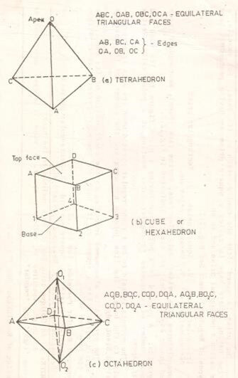
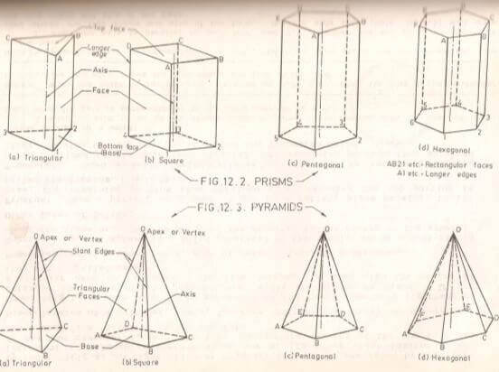
Polyhedra- The solid which is bounded by plane surfaces or faces is called polyhedron. The polyhedra are further sub-divided into three groups, namely regular polyhedral, prisms and pyramids.


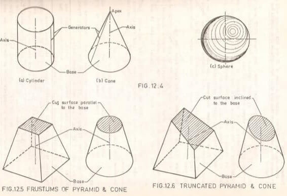
Solids Of Revolution- If a plane surface is revolved about one of its edges, the solid generated is called a solid of revolution. Example cylinders, cones, spheres etc.

Projection Of Solids Assignment Help By Online Tutoring and Guided Sessions from AssignmentHelp.Net
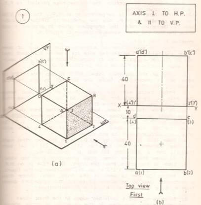
To understand the projection of solids let’s look at the steps to draw top and front views of a cube of 40 mm side resting with one of its square faces on H.P. such that one of its vertical faces is parallel to and 10mm in front of V.P.
1. Look at the pictorial view. Top face ABCD and bottom face 1234 are connected by four vertical faces (lateral surfaces) bounded by vertical edges A1, B2, C3 and D4.
2. To obtain the projections of the cube, first draw the projections of its top face ABCD and bottom face 1234. Then connect them by straight lines in correct sequence, i.e., join the projections of the edges A1, B2, C3 and D4.
3. Decide the view to be drawn first. In this problem the cube rests with a face on H.P. hence its axis is perpendicular to H.P. so, the end face is seen in true size in the top view. Hence, draw the top view first.
4. Look at the cube from the top. Cube rests with a face on H.P. So top face ABCD is parallel to H.P. and an edge CD of a vertical face is parallel to and 10 mm in front of V.P. So draw the top view abcd, a square of 40 mm side with its edge cd parallel to and 10mm below XY.
5. Bottom face 1234 is hidden by the top face ABCD. So in the top view mark the bottom face as (1)(2)(3)(4) such that (1) and a coincide, (2) and b coincide etc. Thus complete the top view.
6. To draw the front view, draw the projectors from the top view.
7. Look at the cube from the front. Bottom face 1234 is on H.P. So draw the front view of the bottom face as 1’2’3’4’ on XY.
8. Height 40 mm is seen in front view. Therefore draw a horizontal line 40 mm above XY to cut the projectors drawn from a, b, c and d at a’, b’, c’ and d’ respectively.
9. To draw the visible and invisible edges in the front view, look at the top view in the direction of the arrow shown. The face ab(2)(1) is nearer to the observer and hence visible. Therefore draw a’b’2’1’ by thick line in the front view.
The face dc(3)(4) is invisible and hence mark this as (d’)(c’)(3’)(4’) in the front view. The invisible edges (4’)(3’), (3’)(c’), (c’)(d’) and (d’)(4’) are hidden by the visible edges 1’2’, 2’b’, b’a’ and a’1’ respectively in the front view and hence not shown in dotted lines.


