LabSim Exercise Week 1
1. Introduction
What is the purpose?
The purpose of lab exercises in this week is to familiarize you with the LabSim environment and review the basics of connecting network media to a personal computer. You will be completing the assigned tasks by using LabSim software. To know more about installing LabSim software, click here.
What are the steps?
- Task 1: In this lab, you will familiarize yourselves with TestOut Hardware Simulator and perform the following tasks:
- Put a hardware component on the workbench.
- Select and identify an item based on its documentation and view.
- Select categories of items.
- Install and uninstall components.
- Set dials and switches.
- Add cable components.
Procedure
- Launch the Network+ LabSim application.
- Select 0.0 Introduction.
- Click 0.1 by using TestOut Hardware Simulator.
- Complete Simulation Exercises 0.1.1–0.1.9.
Lab
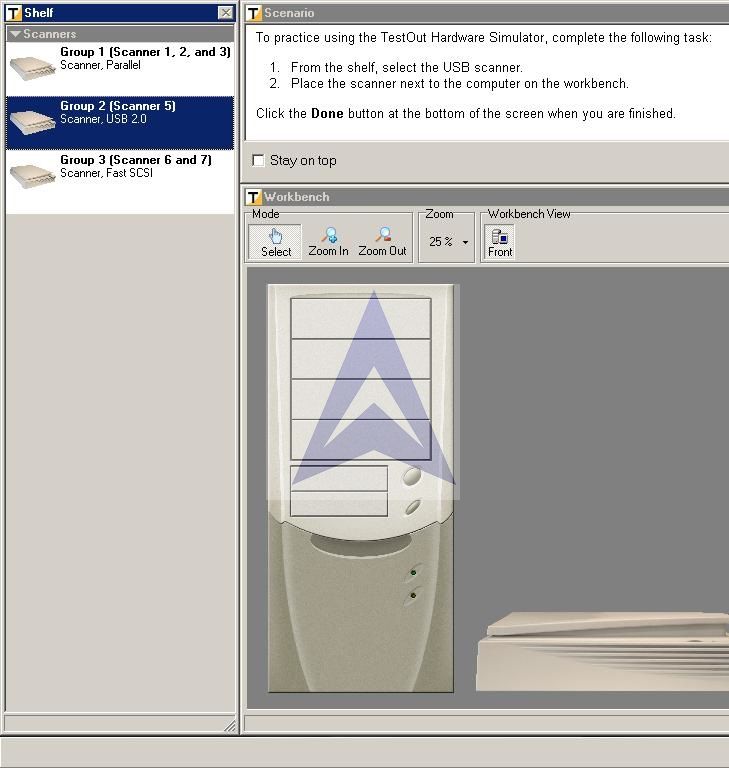
Welcome to the TestOut Hardware Simulator. To begin, notice that your screen is divided into three major areas:
- Scenario (upper right). The Scenario window gives you information about what you need to do (you are currently reading text in the Scenario window).
- Shelf (left side of the screen). The Shelf window lists hardware items that are available for you to install.
- Workbench (bottom right). The Workbench window shows all hardware items that are currently installed.
To practice using the TestOut Hardware Simulator, complete the following task:
- From the shelf, select the USB scanner.
- Place the scanner next to the computer on the workbench.
Click the Done button at the bottom of the screen when you are finished.
Lab
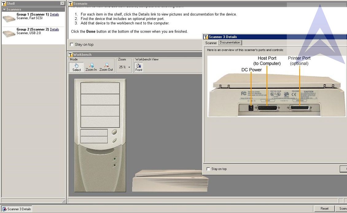
In this simulation, you will learn how to get details about a hardware item on the shelf or workbench. Two types of details are:
- Views. Multiple views of a hardware item are usually available. These views are normally much bigger than the item's icon shown on the shelf.
- Documentation. Some hardware items have documentation that goes beyond the item's description.
To learn how to view and use item details, complete the following task:
- For each item in the shelf, click the Details link to view pictures and documentation for the device.
- Find the device that includes an optional printer port.
- Add that device to the workbench next to the computer.
Click the Done button at the bottom of the screen when you are finished.
Lab
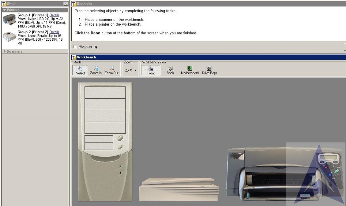
In this simulation, you will learn about categories of items on the shelf. Notice that the shelf has two categories of items: Printers and Scanners. Click each category to see the available items. Notice that categories are listed on the shelf alphabetically.
Practice selecting objects by completing the following tasks:
- Place a scanner on the workbench.
- Place a printer on the workbench.
Click the Done button at the bottom of the screen when you are finished.
Lab
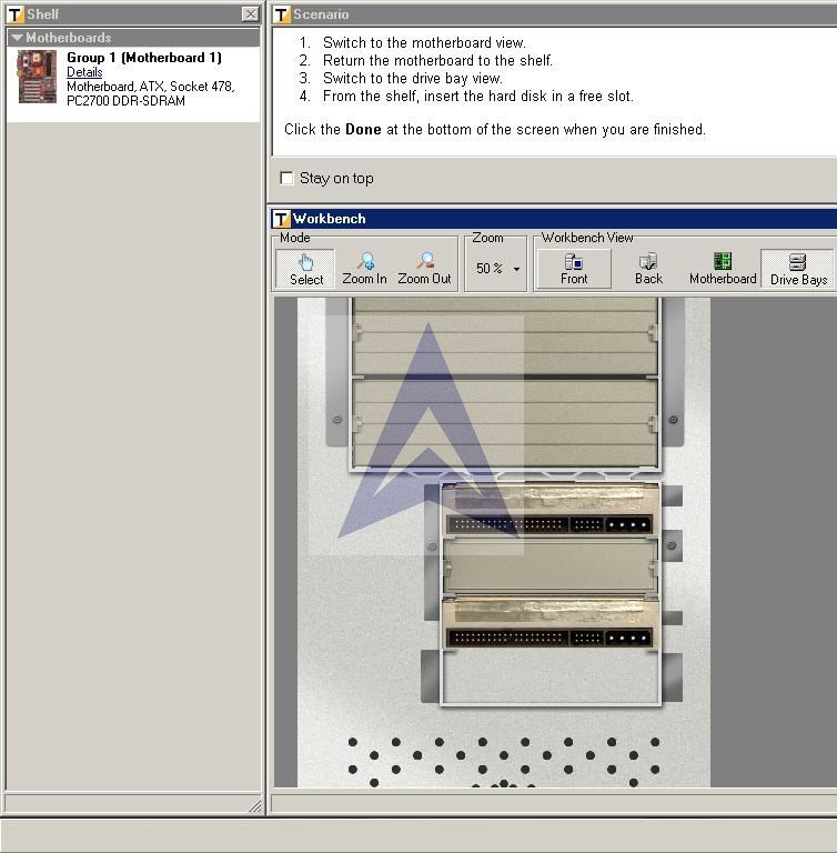
So far, you have learned to put items on the workbench. You can also install hardware components into an existing computer. To learn how to connect and disconnect items, do the following:
- Switch to the motherboard view.
- Return the motherboard to the shelf.
- Switch to the drive bay view.
- From the shelf, insert the hard disk in a free slot.
Click the Done at the bottom of the screen when you are finished.
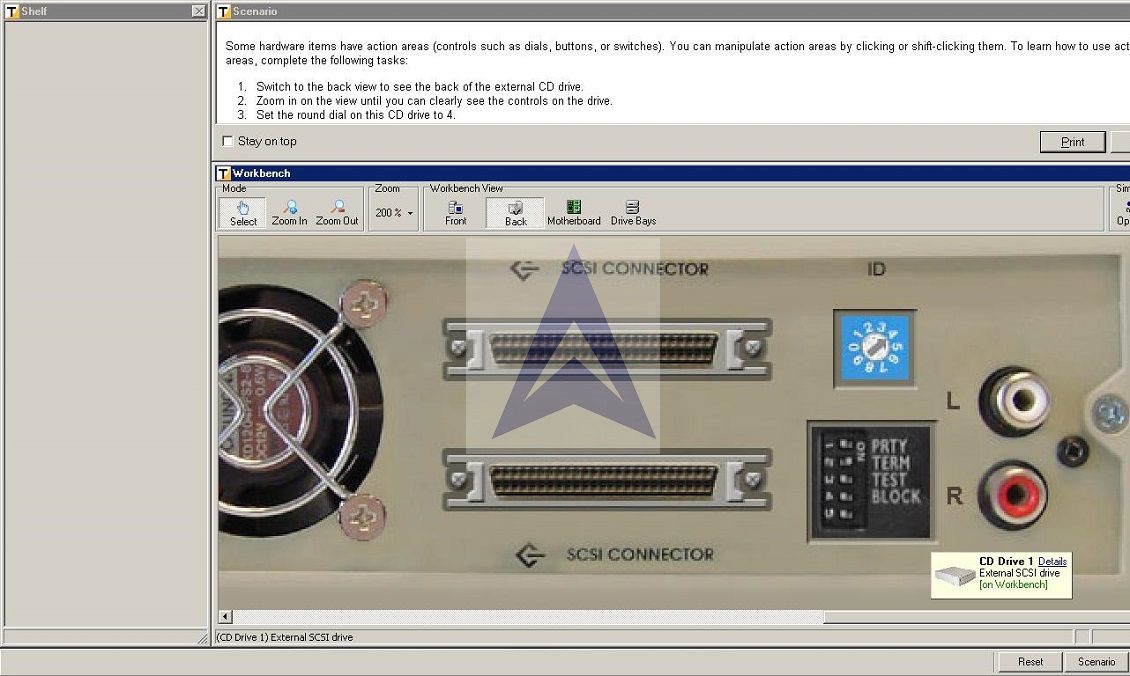
Lab
Some hardware items have action areas (controls such as dials, buttons, or switches). You can manipulate action areas by clicking or shift-clicking them. To learn how to use action areas, complete the following tasks:
- Switch to the back view to see the back of the external CD drive.
- Zoom in on the view until you can clearly see the controls on the drive.
- Set the round dial on this CD drive to 4.
- Put the TERM switch in the ON position (the switch should be pointing to the right).
Click the Done button at the bottom of the screen when you are finished.
Lab
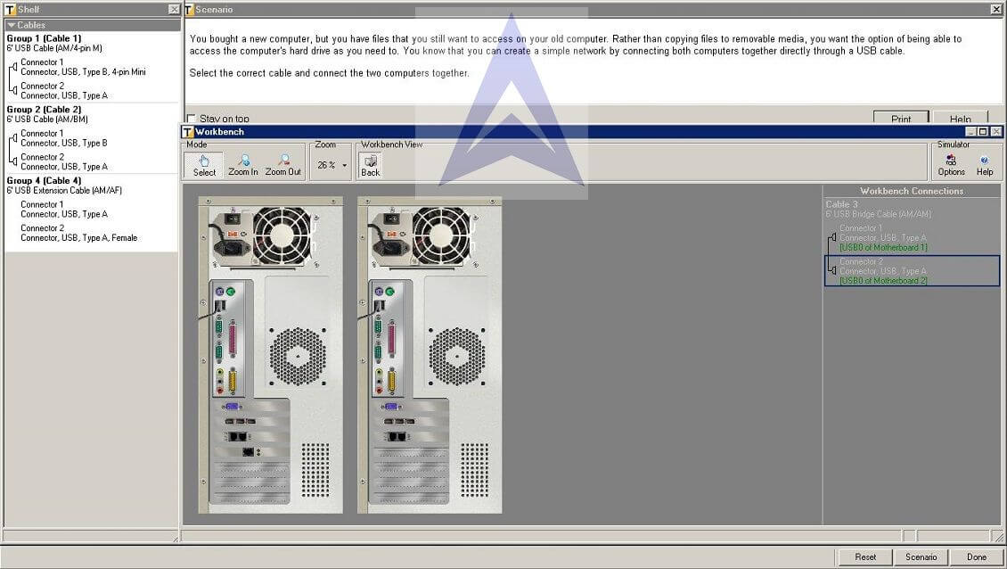
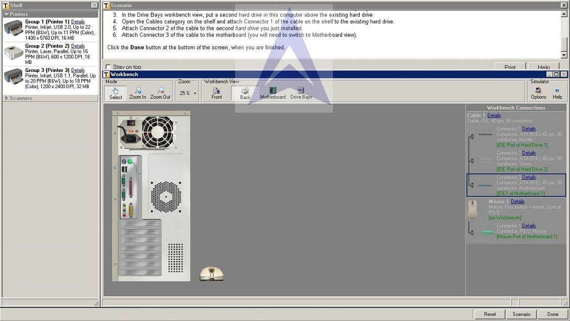
Many hardware devices are connected to the computer, or to each other, using cables. In this simulation, you will learn how to install cabled devices. Cables or items connected with a cable will appear in the following area:
- Workbench Connections. The right side of the workbench shows all cables or devices that include cables. Read the descriptions for each object to identify where the cable is connected.
To learn how to work with cabled devices, complete the following tasks:
- Put a mouse on the workbench.
- Connect the mouse to the computer's mouse port (be sure to switch to the back view of the computer).
- In the Drive Bays workbench view, put a second hard drive in this computer above the existing hard drive.
- Open the Cables category on the shelf and attach Connector 1 of the cable on the shelf to the existing hard drive.
- Attach Connector 2 of the cable to the second hard drive you just installed.
- Attach Connector 3 of the cable to the motherboard (you will need to switch to Motherboard view).
Click the Done button at the bottom of the screen, when you are finished.
- Take a screen shot at the end of each assigned simulation exercise and submit here.
Did it work?
- Were you able to place a hardware component on the workbench?
- Were you able to select and identify an item based on its documentation and view?
- Were you able to select items from the two categories on the shelf, printer and scanner?
- Were you able to install and uninstall hardware components?
- Were you able to set dials, switches, and control buttons properly?
Were you able to install the cable components?
1.0 Cables and Connectors
What is the purpose?
The purpose of this lab is to familiarize you with the process of attaching simulated hardware cables. You will identify how to connect cables to the computer and select and install cables to connect to various computer networks.
What are the steps?
- Task 1: In this lab, you will perform the following tasks to identify and use various cables and connectors to connect to networks:
- Connect to a modem by using a dial-up connection.
- Connect to an Ethernet network.
- Connect fiber optics cables to a network.
- Connect devices using a Universal Serial Bus (USB) connector.
Procedure
- Launch the Network+ LabSim application.
- Select 1.0 Cables and Connectors.
- Complete Simulation Exercises 1.1–1.4.
- Take a screen shot at the end of each assigned simulation exercise and submit here.
Did it work?
- Were you able to connect to a modem by using a dial-up connection?
- Were you able to connect to an Ethernet network?
- Were you able to connect USB networking cables and devices?
Twisted Pair
After finishing this section, you should be able to complete the following tasks:
- Select and install cables for connecting to a dial-up network.
- Select and install cables for connecting to an Ethernet network.
This section covers the following exam objectives:
- 1.4 Recognize the following media connectors and describe their uses:
- RJ-11 (Registered Jack)
- RJ-45 (Registered Jack)
- 1.5 Recognize the following media types and describe their uses:
- Category 3, 5, 5e, and 6
- UTP (Unshielded Twisted Pair)
- STP (Shielded Twisted Pair)
- 1.6 Identify the purposes, features and functions of the following network components:
- Modems
Twisted Pair Facts
Twisted pair cables support a wide variety of fast, modern network standards. Twisted pair cabling is composed of the following components:
- Two wires that carry the data signals (one conductor carries a positive signal; one carries a negative signal). They are made of 22 or 24 gauge copper wiring.
- PVC or plenum plastic insulation surrounds each wire. Plenum cable is fire resistant and non-toxic. It must be used when wiring above ceiling tiles. PVC cable cannot be used to wire above ceilings because it is toxic when burned.
- Two wires are twisted to reduce the effects of electromagnetic interference (EMI) and crosstalk. Because the wires are twisted, EMI should affect both wires equally and can be cancelled out.
- Multiple wire pairs are bundled together in an outer sheath. Twisted pair cable can be classified according to the makeup of the outer sheath:
- Shielded Twisted Pair (STP) has a grounded outer copper shield around the bundle of twisted pairs or around each pair. This provides added protection against EMI.
- Unshielded Twisted Pair (UTP) does not have a grounded outer copper shield. UTP cables are easier to work with and are less expensive than shielded cables.
The table below describes the different unshielded twisted pair (UTP) cable types (categories).
|
Type |
Connector |
Description |
|
Phone cable |
RJ-11 |
Used to connect a PC to a phone jack in a wall outlet to establish a dial-up Internet connection. |
|
Cat 3 |
RJ-45 |
Designed for use with 10 megabit Ethernet or 16 megabit token ring. |
|
Cat 5 |
RJ-45 |
Supports 100 megabit and 1 gigabit Ethernet and ATM networking. |
|
Cat 5e |
RJ-45 |
Similar to Cat 5 but provides better EMI protection. Supports 1 and 10 gigabit Ethernet (gigabit connections require the use of all four twisted pairs). |
|
Cat 6 |
RJ-45 |
Supports high-bandwidth, broadband communications. |
The table below describes the two types of connectors used with twisted pair cables.
|
Connector |
Description |
|
RJ-11 |
|
|
RJ-45 |
|
Each type of UTP cable can be substituted for any category below it, but never for a category above. For example, Cat 6 can be substituted for a task requiring Cat 5e; however, neither Cat 5 nor Cat 3 should be used for this particular task
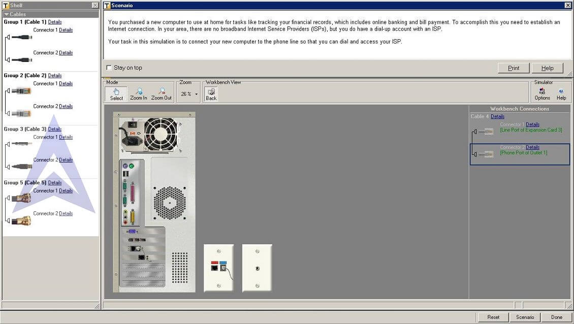
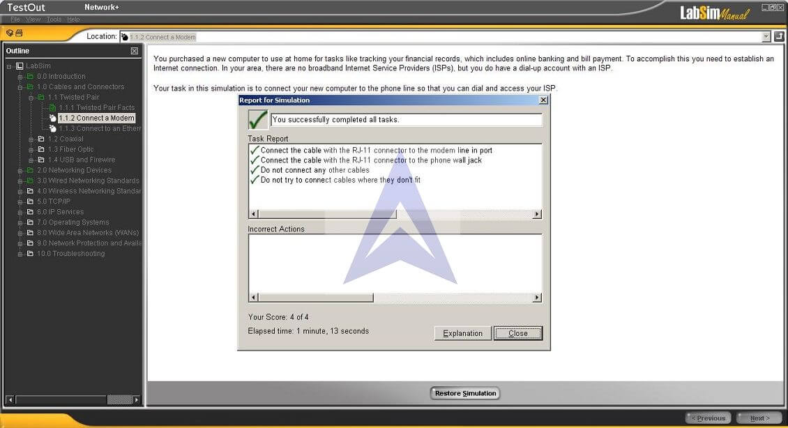
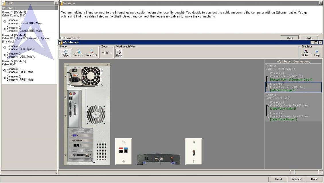
Lab
You purchased a new computer to use at home for tasks like tracking your financial records, which includes online banking and bill payment. To accomplish this you need to establish an Internet connection. In your area, there are no broadband Internet Service Providers (ISPs), but you do have a dial-up account with an ISP.
Your task in this simulation is to connect your new computer to the phone line so that you can dial and access your ISP.
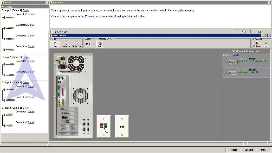
Lab
Your supervisor has asked you to connect a new employee's computer to the network while she is in her orientation meeting.
Connect the computer to the Ethernet local area network using twisted pair cable.
Coaxial
After finishing this section, you should be able to complete the following tasks:
- Select and install components to connect to a cable network.
This section covers the following exam objectives:
- 1.4 Recognize the following media connectors and describe their uses:
- F-Type
- 1.5 Recognize the following media types and describe their uses:
- Coaxial cable
Coaxial Cable Facts
Coaxial cable is an older technology that is usually implemented with a bus topology. It is not suitable for ring or star topologies because the ends of the cable must be terminated. It is composed of two conductors, which share a common axis, within a single cable.
Coaxial cable is built with the following components:
- Two concentric metallic conductors:
- The inner conductor, which carries data signals. It is made of copper or copper coated with tin.
- The mesh conductor is a second physical channel that also grounds the cable. It is made of aluminum or copper coated tin.
- The insulator, which surrounds the inner conductor, keeps the signal separated from the mesh conductor. It is made of PVC plastic.
- The mesh conductor, which surrounds the insulator and grounds the cable. It is made of aluminum or copper coated tin.
- The PVC sheath, which is the cable encasement. It surrounds and protects the wire. It is made of PVC plastic.
Coaxial cable has the following advantages and disadvantages:
|
Type |
Description |
|
Single Mode |
|
|
Multi-mode |
|
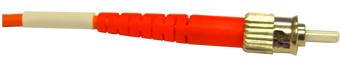
Fiber optic cabling uses the following connector types:
|
Type |
Description |
|
ST Connector |
|
|
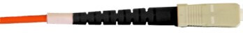
SC Connector |
|
|
LC Connector |
|
|
MT-RJ Connector |
|
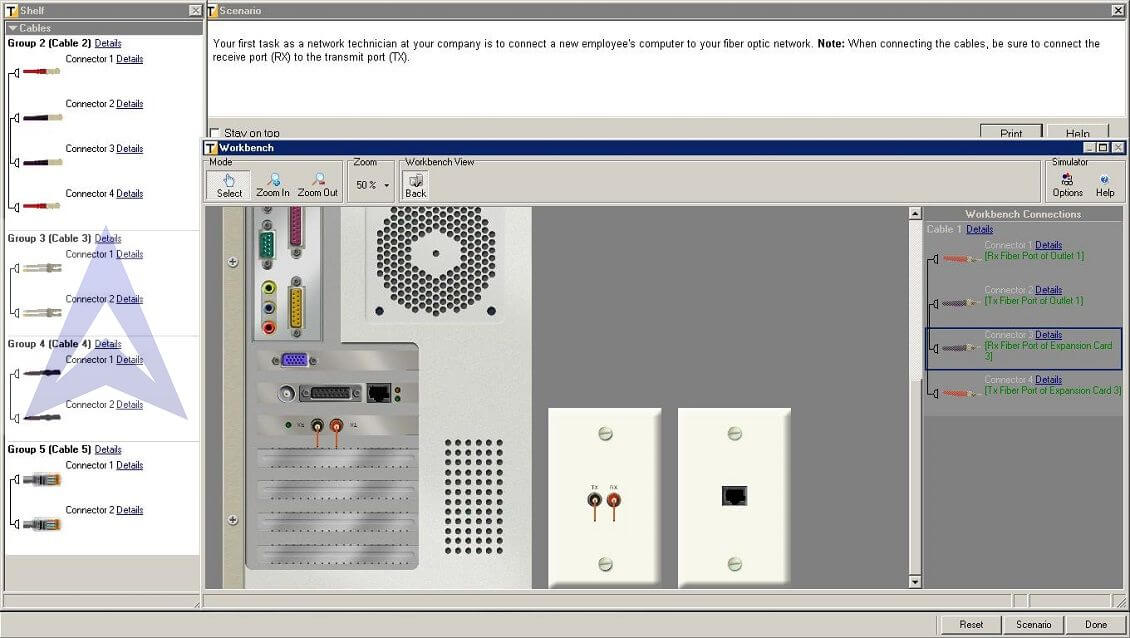
Lab
Your first task as a network technician at your company is to connect a new employee's computer to your fiber optic network. Note: When connecting the cables, be sure to connect the receive port (RX) to the transmit port (TX).
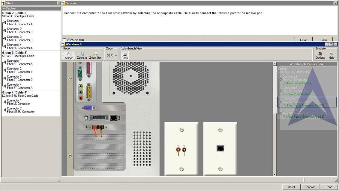
Lab
Connect the computer to the fiber optic network by selecting the appropriate cable. Be sure to connect the transmit port to the receive port.
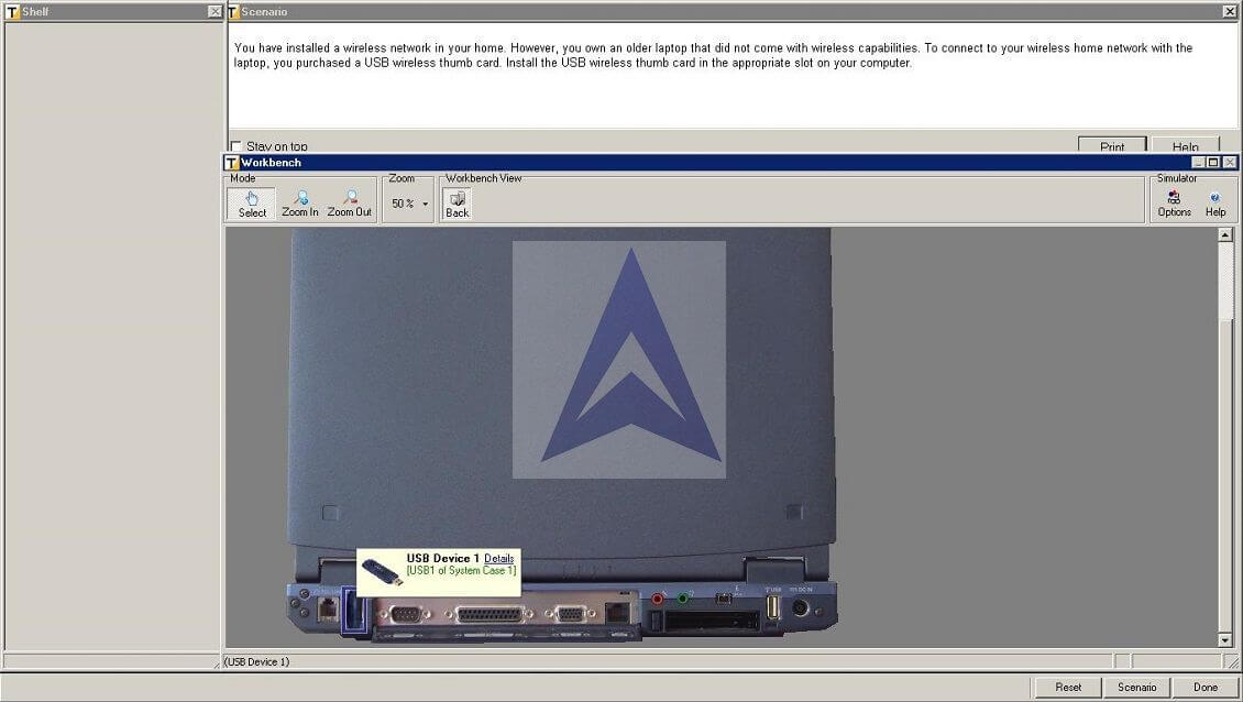
USB and Firewire
After finishing this section, you should be able to complete the following tasks:
- Connect USB networking cables and devices.
This section covers the following exam objectives:
- 1.4 Recognize the following media connectors and describe their uses:
- USB (Universal Serial Bus)
- IEEE 1394 (FireWire)
- Take a screen shot at the end of each assigned simulation exercise and submit here.
Did it work?
- Were you able to connect to a modem by using a dial-up connection?
- Were you able to connect to an Ethernet network?
Were you able to connect USB networking cables and devices?