

Wide band local access wireless lan and wireless atm ieee commu-nication magzine
100 JOURNAL OF COMMUNICATIONS AND NETWORKS, VOL. 6, NO. 3, SEPT. 2004
MADF: Mobile-Assisted Data Forwarding for
| Abstract: |
|---|
data users in a cell, data may suffer long delay, and sys-tem’s quality-of-service (QoS) will degrade. Some tradi-tional schemes such as dynamic channel-allocation scheme (DCA) will assign more channels to hot (or overloaded) cells through a central control system (CC), and the throughput increase will be upper bounded by the number of new chan-nels assigned to the cell. In mobile-assisted data forwarding (MADF), we add an ad-hoc overlay to the fixed cellular infras-tructure and special channels–called forwarding channels– are used to connect mobile units in a hot cell and its surrounding cold cells without going through the hot cell’s base station. Thus, mobile units in a hot cell can forward data to other cold cells to achieve load balancing. Most of the forwarding-channel management work in MADF is done by mobile units themselves in order to relieve the load from the CC. The traf-fic increase in a certain cell will not be upper bounded by the number of forwarding channels. It can be more if the users in hot cell are significantly far away from one another, and these users can use the same forwarding channels to forward data to different cold neighboring cells without interference. We find that, in a system using MADF, under a certain delay requirement, the throughput in a certain cell or for the whole network can be greatly improved.
Index Terms: Wireless data networking, cellular net-work, multi-hop, ad-hoc network, load balancing.
B. Mukherjee is with Department of Computer Science, University of California, Davis, email: mukherje@cs.ucdavis.edu.
The work is supported by NSF grant ANI-0219110, Motorola post-doc grant, CISCO URP; and partly supported by the Teaching De-velopment Grants from the University Grant Council in Hong Kong (HKUST-1-G) and Sino Software Research Institute in the HKUST (SSRI01/02.EG21)
1229-2370/99/$10.00 c⃝ 2002 KICS
Freq. 8
UserE
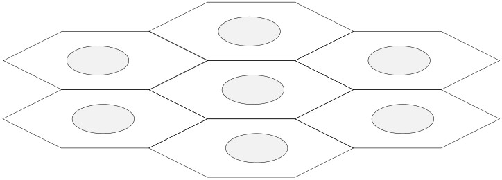
UserG Fig. 2. A simple macrocell/microcell scheme: Frequencies 1-7 are used
in each macrocell , while frequency 8 is used in the microcells overlaid
| Fig. 1. | UserH | in these macrocells. | |
|---|---|---|---|
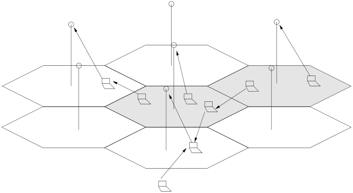
We illustrate in Fig. 1 a wireless data network with MADF, in which we shade the hot cells (i.e., packets expe-
cell/macrocell model. The shaded zones are the overlaid microcells. Since the distance between any two microcells is far enough compared with the microcell radio coverage, all the microcells can use the same frequency, i.e., Freq. 8.
In this research, we are interested in the up-link through-put and delay issues with MADF, for the single cell case and the whole network. To illustrate the improvement in throughput and delay, we consider two access tech-niques for the forwarding channels: Aloha and TDMA. 1 We will also compare the performance of MADF with the traditional schemes such as a DCA scheme and a mi-
1MADF may not bring as much benefit when using CDMA as access technique, since the forwarding channel and the cell channel will use the same bandwidth in such a system.
hot cell exceeds a certain threshold, the host would send its base station a message asking for MADF service. The base station of this hot cell checks its neighboring cells to determine which cell (i.e., which cold cell) the data should be forwarded to. Generally a neighboring cell with the low-
| agents. | More details of this operation will be described |
|
|---|
| improved. | In fact, the routing in MADF may be much |
|---|
C. Paper Organization
This paper is organized as follows. In Sect. II we describe in detail two system operations pertaining to the access of channels: the Aloha and TDMA operations. In Sect. III we present the analysis of the schemes and the maximum cell capacity given a certain packet delay requirement. In Sect. IV, we compare the schemes by showing some illus-trative numerical results. We conclude in Sect. V.
A mobile host which is willing to forward data packets first sends a message to the base station of its cell (we refer the cell where the agent is as the“agent” cell) indicating its availability as a forwarding agent to others. Each base stations monitor the cell traffic load by collecting the delay reports from its users. The traffic information is sent to its neighboring cells so that a cell with a heavy load knows if
and positions. With the help of GPS technology [25], it is possible for the cellular network to know the precise po-sition for each mobile host. In case GPS is not available, by the cellular position technology, the base station at least knows which section of a cell a mobile host resides in. With the knowledge of precise positions or sections of each mo-bile host, the base station of the hot cell can select proper agents for its MADF users. More than one agent will be se-lected, since the connectivity between the mobile host and the best agent selected by the base station may actually do not exist (e.g., due to the complex radio propagation envi-ronment). Mobile host determine which agent to be used referring to its local connectivity. Redundant agents may also be useful for routing robustness. When an agent in MADF suddenly cannot function well because it switches off or makes a large move, the host can forward data to another agent while it sends a report of the routing failure to the base station. Compared to the normal ad hoc rout-ing protocols, the routing in MADF is simpler and more efficient since it excludes the complicated routing discovery procedures for most ad hoc routing protocols.
its packet delay in the data channel. At the meantime, transmitted to the agent, which in turn relays this ACK to
the host builds its local connectivity by exchanging “hello”[24] messages with its neighbors who are within the cover-age of the forwarding channel. If the packet delay in the
slots” (see Fig. 3 (b)) and the first slot as the control slot,
| request |
|
|
|---|---|---|
| subslot | ||
|
| control slot | forwarding slot1 | forwarding slot2 |
|
forwarding slotN |
|---|
connecting request to its agent, indicating which slots are free (i.e., without co-channel interference) around it by lis-tening to the forwarding channel. Agent sends back a reply telling the user which forwarding slot to be used based on the free forwarding slots detected by both the user and the agent. In case there are no free slots, agent may ask user to stop using MADF, or randomly pick a slot. It may happen that when an agent receives a packets, it cannot find a free slot in its “agent” cell immediately. In this case, the agent will buffer the forwarded packet until it contends success-
| RF channel assigned to each cell. | The time on the RF |
|
|---|
Since TDMA is a connection-oriented network, it is al-ways true that grouping the channels (slots) by a larger number to serve more users has better performance. When using MADF with TDMA, traffic in the hot cell is not in-tentionally split into different kinds of slots, e.g., data slots and forwarding slots, as is done in the Aloha MADF. Any new user in a hot cell will be randomly assigned a data slot or told to use a forwarding slot. The maximum number of the forwarding slots to be used in this hot cell is calculated by the base station according to the lowest QoS require-ment (the average delay) and the traffic in the neighboring cells. When no data slots are available, and the number of the forwarding slots used in the hot cell doesn’t reach the maximum number, the base station will inform the new user through the down-link channel to use a forwarding slot. It should be noticed that the base stations only de-cide how many forwarding slots should be used in MADF, while they don’t decide which forwarding slots should be used. The forwarding slots are picked by mobile agents. Thus, for a mobile user using MADF, it may access any of the forwarding slots in the forwarding frame.
III. System analysis
104 JOURNAL OF COMMUNICATIONS AND NETWORKS, VOL. 6, NO. 3, SEPT. 2004
A B C
.
PKT1
ACKB .
the injection process of newly-arriving and back-logged .
ACKC
Let E be the average number of retransmission attempts
Define τ as the packet transmission time. We assume that the retransmission timeout, defined as the delay from the time we know the packet is not delivered (i.e., the ab-sence of an ACK after a round-trip delay) to the start of the next transmission, to be uniformly distributed between 0 and k−1 times of the packet transmission time. The maxi-mum timeout is hence (k−1) times the packet transmission time, which is (k−1)τ. By noting that each retransmission takes a total time of (1 + R + (k − 1)/2) × τ, the average delay, d, is then clearly given by the sum of the packet transmission time and round-trip time for the ACK, i.e.,
Therefore, the average delay for each hop in the forwarding channel is the same; therefore in an n-hop MADF, the de-lay over the whole channel is simply the delay over a single link multiplied by n. Thus, Df can be calculated.
|
|
(4) |
|---|
| population. | Du, the delay that takes users to transmit |
|
|
(5) |
|---|---|---|---|---|
| data to their own base station, can be calculated directly. | λ = Ge−G. | |||
| To find the delay in the forwarding channel, i.e., Df, we | ||||
| show in Fig. 4 the end-to-end protocol operation with an | (6) | |||
| intermediate agent B. A is the sender while C is the base | ||||
| station in the agent cell. The data packets first have to be | ||||
| transmitted successfully to agent B, which in turn forwards | ||||
The factor 0.5 in the above equation is due to the fact that each packet has to wait for an average of 0.5 packet trans-mission time before it is aligned with the slot boundary and can be transmitted. E is obviously given by
E = G/λ − 1 = eG− 1. (7)
large number of packets to transmit continuously. We con-sider that the slot-request signal can always be transmitted successfully, and there is no re-transmission delay for the
Define Du to be the average delay that User A expe-riences in having its first data packet received by either
| slot-request signal. As usual, we are interested in the sys- | (12) | |
|---|---|---|
| tem throughput and users’ access delay (defined as the time | ||
| from the instance of the arrival for the first packet of the | ||
| data burst, until the time it is delivered to a base station). |
When a new user in the hot cell, say User A, starts to transmit data, it has to wait for an average time of t1 for the control slot, i.e.,
With M forwarding slots to be used and the throughput of P in each forwarding slot, a throughput of MP is for-warded to the cold neighboring cell. Since the local load in the neighboring cell is 0, as we assumed at the beginning of the analysis, with the assumption that each data slot in the cold cell is assigned with the same forwarded traf-fic, the utilization of each data slot in the cold cell then is MP/N. Similar to Eqn (12) with the number of available slots modified as N and the data slot utilization modified as MP/N, define Dc to be the access delay that agents
| t1 = τf/2. | (8) | ||
|---|---|---|---|
| In the control slot, User A will send the slot-request. Since there is no collision for slot-requests, the slot-request | Dc = τf/(1 − (MP/N)N) + τs. | (13) | |
| request. If at that time there is no slot available, User A | Df = Du + Dc. | (14) |
|---|---|---|
| has to wait for the following frames until it gets a free data |
slot or a forwarding slot. Assuming that each of the N data slots and M forwarding slots have the same slot utilization P, where P can also be considered to be the normalized throughput in each slot, the probability that User A can or cannot find a free slot (a data slot or a forwarding slot) is 1 − PN+Mor PN+M, respectively. Define E the average
Define D the average access delay for the users in the hot cell. Since a throughput of NP is transmitted to the hot cell directly with the average delay of Du and a throughput of MP is transmitted to the cold cell with the average delay of Df, then:
| number of frames that user A has to pass before a frame | (15) | |||
|---|---|---|---|---|
| comes, during which User A can get access to a data slot | ||||
| or a forwarding slot after it has successfully sent the slot- |
In such a TDMA MADF, when the local traffic in the cold cell is not 0, the access delay can also be calculated. If
| E | = | ∞ � |
|
|||
|---|---|---|---|---|---|---|
| = | ||||||
|
||||||
|
(9) | |||||
| (16) | ||||||
| and | t2 = Eτf. | (10) | ||||
number of the forwarding slots to be used can be deter-mined so that the optimum system throughput can be achieved under a delay constraint.
IV. Numerical Results and Comparison
| t3 = | N+1� | iτs | N= (N + 2) | (11) | ||
|---|---|---|---|---|---|---|
|
||||||
| i=2 |
4 4
the round-trip propagation delay is very small and can be 3
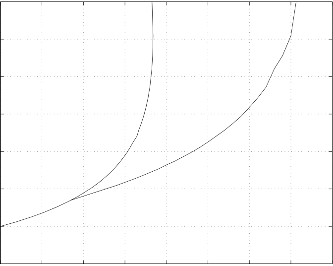
In Fig. 5, we show the maximum throughput in a pure- 0: Pure Aloha without MADF
1: Pure Aloha with one−hop MADF
0 0.05 0.1 0.15 0.2 0.25 0.3 0.35
0.15, the average delay D increases slowly. After that, D Throughput
| a single cell with one pure-Aloha channel is 0.15. When | Table 1. |
|---|
throughput in a cell approaches this point, users in that cell have to use MADF to split the traffic. It should be noted that ˆD can be any other value due to different QoS
macrocell/microcell network. (First number in each entry is with delay constraint; the second number is without delay constraint.)
| schemes | MADF | DCA | Macro-micro |
|---|
| requirements, but the analysis will still hold. In Fig. 5, the | λS | 1.50/1.80 | ||
|---|---|---|---|---|
| λC | 0.30/0.36 | |||
| cross point of the two curves at λ = 0.08 is the throughput |
threshold value at which a user should stop using MADF
since, below this point, MADF cannot bring any through-put enhancement. When ˆD = 3, there is 47% throughput
forwarding channel, the dynamic channel or the microcell
| Average delay | 6 |
|
||||||||
|---|---|---|---|---|---|---|---|---|---|---|
| 5 | ||||||||||
| 4 | ||||||||||
|
||||||||||
| 3 | ||||||||||
|
||||||||||
| 2 | ||||||||||
| 1 | ||||||||||
| 0.05 | 0.1 | 0.15 | 0.2 Throughput |
0.25 | 0.3 | 0.35 |
|
|||
| Fig. 5. | ||||||||||
|
||||||||||
|
||||||||||
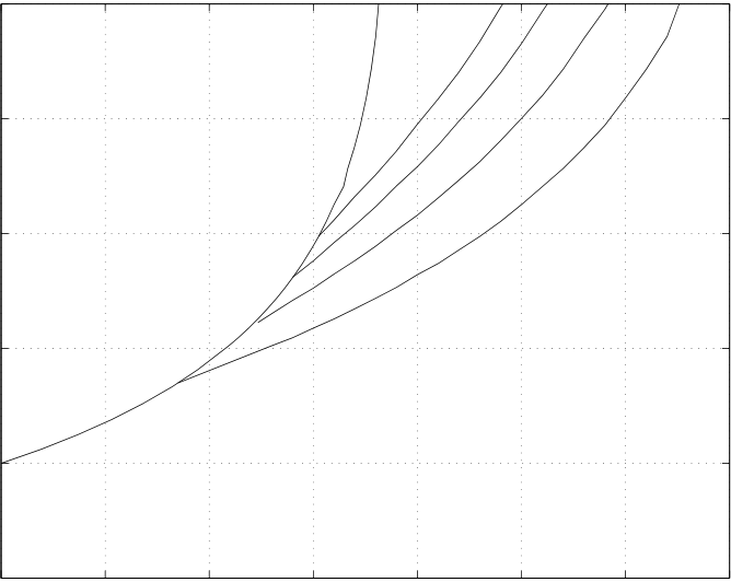
If the traffic in a hot cell can only be split to a cold cell through a multi-hop MADF, the average delay in the forwarding channel increases. Compared to the network with one-hop MADF, networks with multi-hop MADF have larger average delay. Under the same ˆD, the multi-hop MADF schemes achieve lower throughput increase, while if we relax the value of ˆD, we can still achieve high
| throughput enhancement. | The throughput improvement |
|---|
with multi-hop MADF is shown in Fig. 6, which shows multi-hop MADF improves the delay-throughput perfor-mance and the cell with fewer hops of MADF has the larger throughput under the same ˆD. The cross points of the curves show the throughput threshold values under which a user should not use multi-hop MADF.
Now we compare the throughput improvement in a MADF network, a dynamic channel-allocation (DCA) net-
| MADF: MOBILE-ASSISTED DATA FORWARDING FOR WIRELESS DATA NETWORKS | TDMA without MADF | 107 | |||
|---|---|---|---|---|---|
| ber of slots in each frame increases, the maximum channel utilization increases because more of the channel is used | 25 | ||||
| as data slots, and the delay decreases at the high channel | |||||
| utilization but increases at low channel utilization. Com- | 20 |
|
|||
| pared with slotted Aloha, with a looser delay constraint, | |||||
| TDMA can achieve higher channel utilization. Specifically, | Average delay |
|
|||
| TDMA can achieve a channel utilization larger than 0.36 | |||||
| while slotted Aloha cannot. Note that there is a minimum | |||||
| delay for both TDMA and slotted Aloha even when chan- | |||||
| nel utilization is close to 0 because packets have to wait for the slots. | 5 | ||||
| ment when using MADF in a TDMA network with frame | 1 | 2 | 3 | 4 Throughput |
5 | 6 | 7 | 8 | |
|---|---|---|---|---|---|---|---|---|---|
| size of 6 slots. When users in a hot cell use one-hop MADF |
to forward data to one of its cold neighboring cells whose the local load is 0, with different number of the forwarding
Fig. 8. Delay-throughput comparison between a TDMA cell without
| slots used in MADF, the throughput improvement in this | 25 | |
|---|---|---|
| hot cell is shown in Fig. 8. The crossover points between | ||
| the curve without MADF and the curves with MADF in | ||
| the figure show the throughput threshold values over which | 20 |
| relatively large delay, i.e., when delay is larger than 10 in | Average delay |
|
with MADF and Pc=0.3 |
|
|---|---|---|---|---|
| Fig. 8, throughput increases when the number of used for- | ||||
| warding slots increases. At a delay value of 15, there is an | ||||
| approximately 20%, 38% and 57% of throughput improve- | ||||
| ment over a normal TDMA cell by using MADF in TDMA |
|
|
1 | 2 | 3 | 4 Throughput |
6 | 7 | ||
|---|---|---|---|---|---|---|---|---|---|
|
|
Slotted Aloha | TDMA with 6 slots | |
|---|---|---|---|---|
|
||||
|
||||
|
0.1 | 0.2 | 0.3 | 0.4 Channel utilization |
|
0.6 | 0.7 | ||
|---|---|---|---|---|---|---|---|---|---|
In Fig. 9, we show the throughput improvement for a TDMA cell using MADF when there is different local load Pc in its agent’s cell. Three forwarding slots are used. When there is a light load (Pc = 0.3) in the agent’s cell, the throughput improvement is very close to that when there is no load in the agent’s cell. When there is a moderate load (Pc = 0.5) in the agent’s cell, less throughput improvement can be achieved.
Finally, we use simulation to examine the performance of MADF in a 7×7-cell two-dimensional cellular network (Fig. 10). A network with a larger size has the similar simulation results. For this simulation, there are 30 channels in each cell, and the cluster size for frequency reuse is 4, i.e., the
| 108 |
|
|
|---|---|---|
| forwarded data to its own base station. With the analyti- |
cal models and the simulation model we built for MADF,
| A | C | B | D | A | C | B | D | A | C | B | D | A | ||
|---|---|---|---|---|---|---|---|---|---|---|---|---|---|---|
| A | B | A | B | A | B | A | ||||||||
|
||||||||||||||
|
| A | C | B | D | A | C | B | D | A | C | B | D | A | ||
|---|---|---|---|---|---|---|---|---|---|---|---|---|---|---|
|
||||||||||||||
| A | C | B | D | A | C | B | D | A | C | B | D | A |
|
|
| Average delay | Fig. 10. | A 7 × 7-cell TDMA network model. |
|
|
|||||||
|---|---|---|---|---|---|---|---|---|---|---|---|
| References | |||||||||||
| [1] | |||||||||||
|
|||||||||||
|
|||||||||||
| [2] | |||||||||||
|
|||||||||||
| [3] |
|
||||||||||
|
|||||||||||
| [4] |
|
||||||||||
|
|||||||||||
|
20 | 21 | 24 | 25 | 26 | ||||||
| [5] | |||||||||||
|
19 |
|
|||||||||
| Fig. 11. | Delay-throughput comparison in a 7 × 7-cell TDMA network | [6] | |
|---|---|---|---|
|
|||
proceedings-Communications, vol. 144, pp. 205–210, 1997.
| out MADF. When the cell throughput is high, the delay in | [8] | |
|---|---|---|
| [9] |
|
|
| the system with “in-band” MADF is the highest. The “in- | ||
|
||
| band” MADF can thus improve system performance be- | ||
“Call blocking performance of distributed algorithms for dy-namic channel allocation,” IEEE Transactions on Communi-cations, vol. 42, pp. 2600–2607, Aug. 1994.
[10] R.Saunders and L.Lopes, “Performance comparison of global and distributed dynamic channel allocation algorithms,” in Proceedings of IEEE Vehicular Technology Conference (VTC), vol. 2, pp. 799–803, June 1994.
[16] K. Pahlavan, A. Zahadi, and P. Krishnamurthy, “Wide band local access: Wireless LAN and wireless ATM,” IEEE Commu-nication Magzine, pp. 34–40, Nov. 1997.
MADF: MOBILE-ASSISTED DATA FORWARDING FOR WIRELESS DATA NETWORKS 109
[21] X. Wu, B. Mukherjee, and G.-H. Chan, “Maca-an efficient chan-nel allocation scheme in cellular networks,” in IEEE proceedings of Globcom, vol. 3, pp. 1385 – 1389, 2000.
 |
|
|
|---|---|---|
| ington, Seattle, in June 1987. | In July 1987, | |
hoc, 2002. of the textbook ”Optical Communication Networks” published by
[23] B. Bhargav, X. . Wu, Y. Lu, and W. Wang, “Cellular aided mobile wireless network (cama),” Accepted for MONET Special Issue on Integration Heterogeneous Wireless Technologies.
 |
|
|
|---|---|---|
| he joined Arraycomm Inc. | as a protocol re- | |
|
||
 |
|||
|---|---|---|---|
| in business administration. | He obtained his | ||
| tems. | He is currently an Assistant Professor | ||
 |
|
||
|---|---|---|---|
| sity. | He is a professor of computer sciences | ||
| at Purdue University. |
|
||


