Time for tall ellipse plot xlabel ylabel title
MAE 560 Fall 2020
Project 3
Luca RobbinsStatement of Collaboration:
|
|

| (1) |
|---|
| From Ansys From Setup From Setup From Ansys |
|
|---|
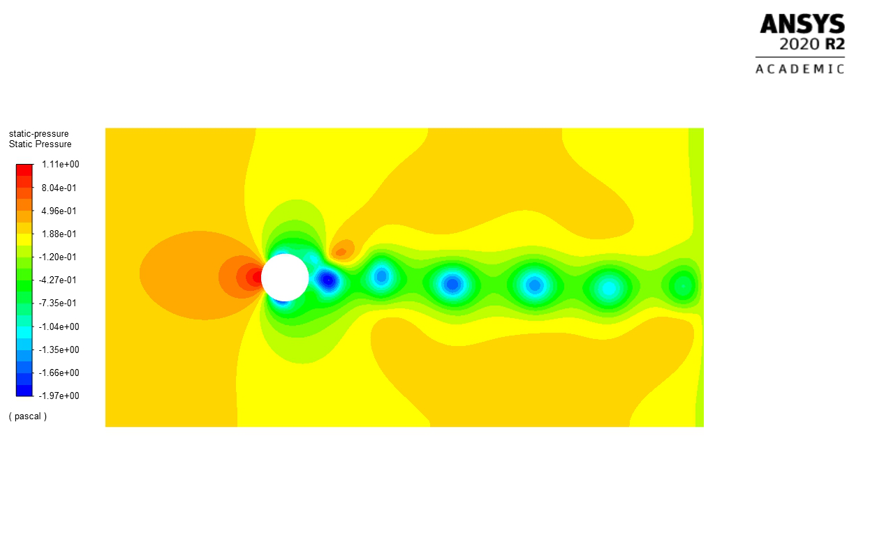
II) Contour plots of static pressure, y-velocity and stream function @ t = 3 min
Figure 1 Static Pressure over Circle in Flow
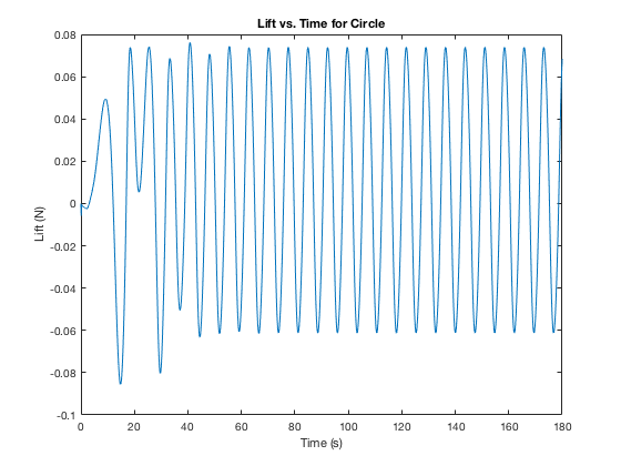
Figure 4 Lift vs. Time for Circle in Flow
The plots above were utilized to find the amplitudes and periods of oscillation. The MATLAB code used is in the Appendix.
IV) Comparison of Amplitude and Period of Shapes in Flow
| Amplitude of Lift (N) | Period (s) | |
|---|---|---|
| 0.067525 | 7.3 | |
|
0.13935 | 8.6 |
|
0.027145 | 5.4 |
Figure 7 Mesh along plane of symmetry with Angle of Attack @ 40 Degrees
Figure 8 X Velocity @ 0 degree Angle of Attack
| Lift Force (N) | Drag Force (N) | |
|---|---|---|
| q= 0° | 5.8246 | 5.2487 |
| q= 20° | 65.906 | 19.382 |
| q= 40° | 53.661 | 62.888 |

Task 3:
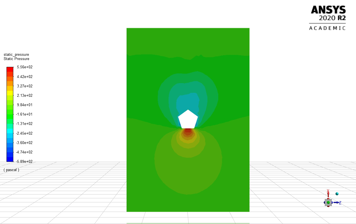
Pentagon Shaped Building in freestream flow. The first set has the flow moving from bottom to top and the second set has the flow moving top to bottom.
Figure 13 Static Pressure on Horizontal Plane Pointed Side
Figure 14 Velocity on Horizontal Plane Pointed Side
| Total Drag (N) | Pressure Drag (N) | Viscous Drag (N) | |
|---|---|---|---|
| 755.901 | 754.879 | 1.0219 | |
| 1164.04 | 1163.70 | 0.3327 |
The general expectation was that the flat side of the pentagon would generate more drag given it is more of a bluff body, but this was not the case. By looking at the drag table, it is clear that the pointed side facing into the wind led to a higher magnitude of drag. We can then analyze this in the pressure and velocity plots above. In Fig. 13, it can be seen that there is a much larger low pressure region than there is in Fig. 11 behind the pentagon. This low pressure region has a direct effect on the drag being generated on the structure. In addition, when comparing Fig. 12 and 14, it can be seen that the velocity in the system is lower in magnitude, thus generating more drag which slows the entire system down. This is similar to what you see in wind tunnels when an airfoil changes angle of attack, the entire flow through the tunnel slows down. It seems that the pointed side of the pentagon creates a sort of fast-back design, where the flow is more gradually returned to the flow over the back surface of the pentagon, thus reducing the drag on the object. This type of design can be seen most notably on cars as well as supercritical airfoils.
The more abrupt back surface creates a very turbulent region on the back side of the pentagon, thus greatly increasing the drag.
Tc=Circle.data(:,2);
Tt=Tall.data(:,2);
Tl=Long.data(:,2);figure(1)
plot(Tc,Lc)
xlabel('Time (s)')
ylabel('Lift (N)')
title('Lift vs. Time for Circle')


