

The two ends bulb filament and current through the terminal pair
| 10 | C H A P T E R |
|
t h e | c i r c u i t |
|
|---|---|---|---|---|---|
| 2. | Choose lumped element boundaries so that there is no total time varying | ||||
| ∂q | |
|---|---|
| ∂t |
3. Operate in the regime in which signal timescales of interest are much larger than the propagation delay of electromagnetic waves across the lumped elements.
The intuition behind the first constraint is as follows. The definition of the voltage (or the potential difference) between a pair of points across an element is the work required to move a particle with unit charge from one point to the other along some path against the force due to the electrical field. For the lumped abstraction to hold, we require that this voltage be unique, and therefore the voltage value must not depend on the path taken. We can make this true by selecting element boundaries such that there is no time-varying magnetic flux outside the element.
| 1.3 The Lumped Matter Discipline |
|
11 |
|---|
Instead, we fix the problem created by the finite propagation speeds of electromagnetic waves by adding the third constraint, namely, that the timescale of interest in our problem be much larger than electromagnetic propagation delays through our elements. Put another way, the size of our lumped elements must be much smaller than the wavelength associated with the V and I signals.10 Under these speed constraints, electromagnetic waves can be treated as if they propagated instantly through a lumped element. By neglecting propagation
+
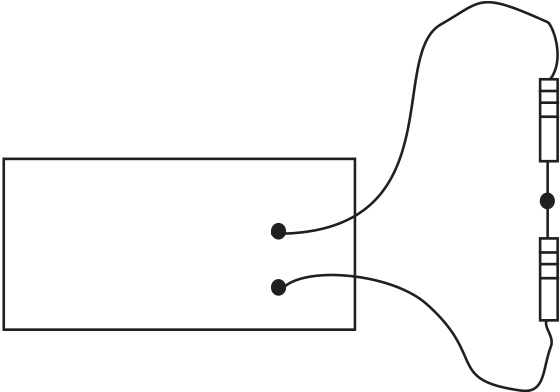
| Signal | v(t) | R1 | FIGURE 1.7 Resistor circuit | ||
|---|---|---|---|---|---|
|
|||||
| generator | R2 |
|
|||
| - | |||||


