


CE2003 Structural Mechanics / Structural Concrete Design 55
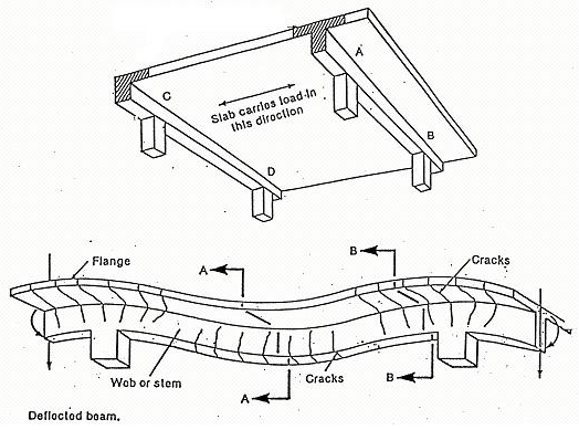
T-section
L-section
Actual
N.A.
Fig. 2.5-3 Stress blocks of T-beams. (a) Actual stress block; (b)
equivalent stress block
CE2003 Structural Mechanics / Structural Concrete Design 57
| neutral axis |
s = 0.8x
|
Fcc |
|
Stress block |
| where |
.0 87 f z yk
|
(2.10) |
| and |
K M |
|
|
2.5.3Analysis of a flanged section with the depth of stress
block lying
CE2003 Structural Mechanics / Structural Concrete Design 58
| hf= 150 mm |
|
s = 0.8x
|
Fcc |
| As =1470 mm2 |
| Section |
For equilibrium: Fcc = Fst
therefore
| so |
|
|
.0 567 |
|
25 |
|
|
| x |
|
56 |
mm |
fh |
|
|
| |
s / |
8.0 |
|
70mm
|
CE2003 Structural Mechanics / Structural Concrete Design 59
Taking moments about the centroid of As,
the moment of resistance is
check the depth of the stress block extends below the flange. An
alternative
'
procedure is to calculate the moment of resistance, M , of the section
with f
s fh , the depth of flange (see Fig. 2.5-4). Hence if
the design moment, M , d
maximum value of x for a singly reinforced
section and concrete class ≤
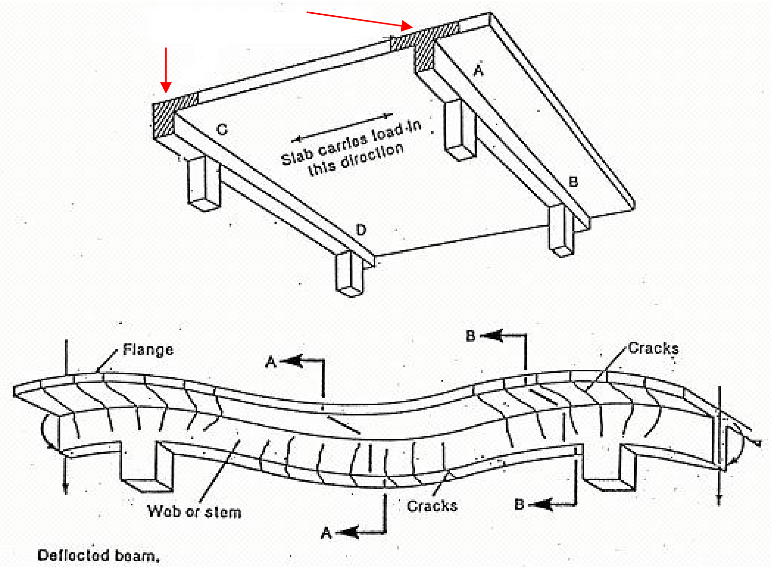
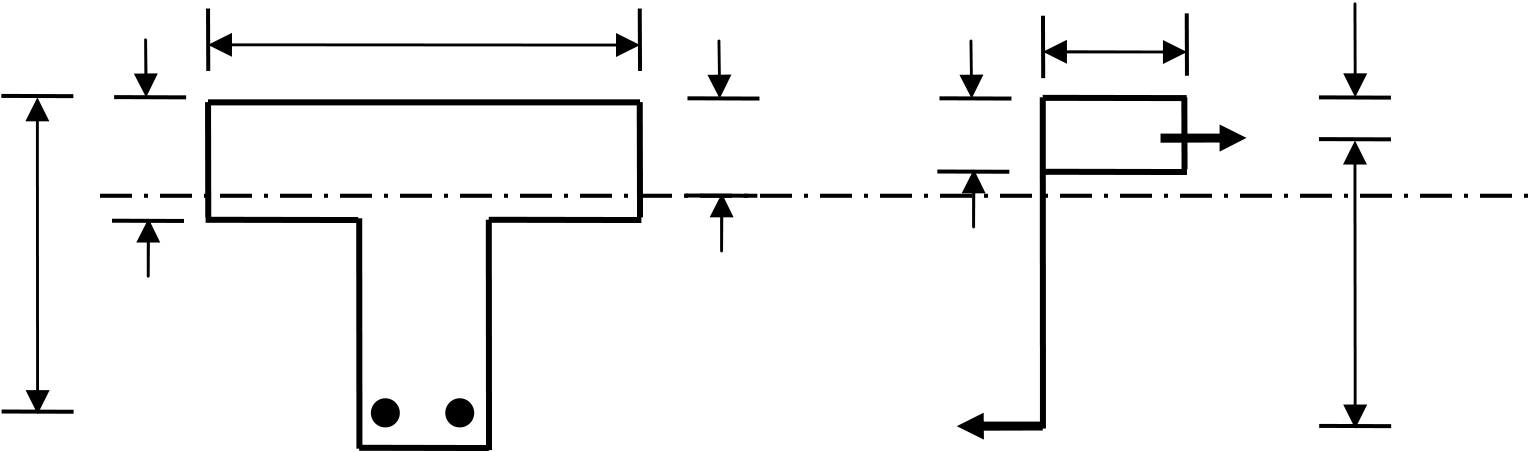
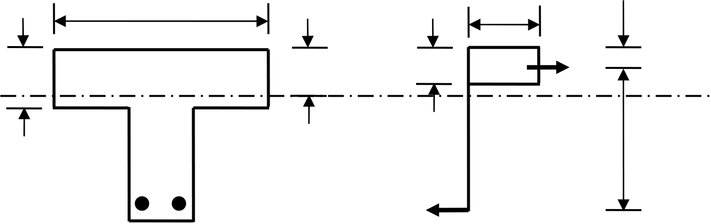
A Tsection (or Lsection) can be divided into flange
component and web
component, as shown in Fig. 2.5-5.
| As |
Asf |
Asw |
|
|
bw |
|
|
moment M-Mf
|
Fig. 2.5-5 Flange and web components of a T-section
| sf |
|
.0 |
87 f ( d yk |
|
5.0 h ) f |
(2.30) |
oMoment of resistance of the web component
|
|
.0 87 f z yk |
.0 87 f z yk
|
(2.32) |
| |
d[ |
5.0 |
|
.0 25 |
|
K |
w |
|
oTotal reinforcement area
| f |
| 170 kNm 180 kNm, the design moment |
CE2003 Structural Mechanics / Structural Concrete Design 62
.0 56725 (400200) 100(3505.0100)
| sf |
|
.0 87 f ( d yk |
|
|
|
|
|
651 mm2
|
| |
85 |
|
10 |
6 |
|
|
.0 87 |
|
500(350 |
|
5.0 |
|
100 ) |
|
|
oFactor for the moment of resistance of the web component:
|
w |
b w |
d f |
ck |
|
|
| z |
|
200 |
|
350 |
2 |
|
25 |
|
|
| |
350 |
[ |
5.0 |
|
.0 25 |
|
.0 155 / .1 134 ]
|
| sw |
|
.0 87 f z yk |
|
.0 87 |
|
500 |
|
293 |
|
|
|
Provide 3T25 (As = 1472 mm2).
(2) Design by the code method (EC 2)
x = 0.45d s = 0.8x

= 0.2fckbwd
Eq. (2.34) is only applicable when hf<
0.36d.
| x |
.0 45d |
|
| M |
|
|
F z c1 1 |
|
F z c2 |
|
Note: when using equation 2.34 to calculate the area of tension steel
As, it is
| f |
| 170 kNm 180 kNm, the design moment |
|
s |
|
.0 87f |
yk |
(d |
|
5.0 h ) f
|
350 |
|
100) |
|
1414mm |
|
| |
180 |
|
10 |
6 |
|
1.0 |
|
25 |
|
200 |
|
350 |
|
( .0 36 |
|
|
.0 87 |
|
500 |
|
(350 |
|
5.0 |
|
100) |
|
|
|
|
|
|
2.5.5Flanged section with compression
reinforcement
When the design ultimate moment
| |
M |
bal |
|
|
2 |
|
.0 567 f (b ck |
f |
|
|
compression steel is required.
The moment (M – Mbal) will be resisted by compression
steel. Hence,
0.87fykAs = compression of flange component + compression of
web component + compression of steel A’s
|
|
.0 87 f |
|
|
| Again, |
d'x |
|
.0 38 |
or |
d'd |
|
.0 171 |
, otherwise the compression steel |
|
.087 fyk |
|


