

The source charging the capacitor
| 912 | C H A P T E R |
|
||
|---|---|---|---|---|
| 16.4 | ||||
16.4.1 P E A K D E T E C T O R
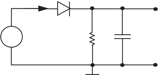
A simple example is shown in Figure 16.11, a circuit identical to the half-wave rectifier already discussed, except for an added capacitor. The output waveform of this circuit will follow the positive peaks of the input wave, so is more efficient for converting AC to DC. The node equation at the vC node is
| iD =vC | + CdvC | (16.5) |
|---|
| vi = Vp sin(ωt) | + vD | C | + | ||
|---|---|---|---|---|---|
| R | |||||
| vC | |||||
| - | |||||
| - |
(a) Circuit
| FIGURE 16.11 Peak detector. |
|
- | R | C | + | |
|---|---|---|---|---|---|---|
| vC | ||||||
| - |
| R | C | + | |
|---|---|---|---|
| vC | |||
| - |
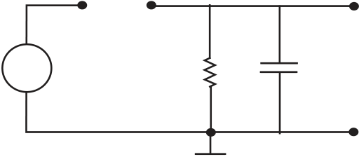
(c) Diode OFF subcircuit
| 16.4 Nonlinear Analysis with RL and RC |
|
913 |
|---|
|
||||||||
|---|---|---|---|---|---|---|---|---|
| dvC | vC | Is | eq (vi−vC)/kT 1 |
|
||||
| dt | = −RC | + C |
|
|||||
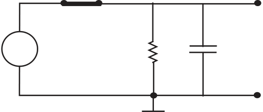
If we model the diode as an ideal diode, then two linear RC subcircuits result, one for the diode ON, and the other for the OFF state, as shown in Figures 16.11b and 16.11c. For the diode ON,
vC = vi. (16.9)
| Diode ON: iD | positive, |
|
|
|---|---|---|---|
| Diode OFF: vD | negative, |
|
| vi < vC. | (16.13) | ||||
|---|---|---|---|---|---|
| iD = | �vC | + CdvC | � | (16.14) | |


