

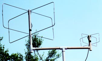
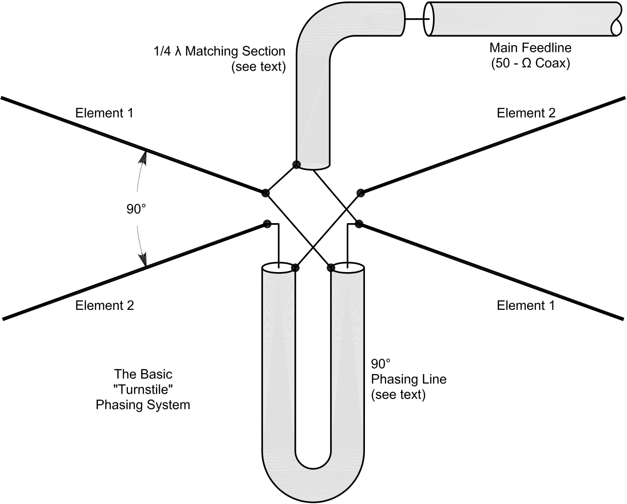
The moxons will fed out phase with phasing line coaxial cable
By L. B. Cebik, W4RNL
A Simple Fixed Antenna for VHF/UHF Satellite Work Explore the low-Earth orbiting amateur satellites with
this effective antenna system.
|
||||
|---|---|---|---|---|
|
||||
| 38 | August 2001 | |||
|
|
|---|
Building the Moxon Pairs
The Moxon rectangle is a modification of the reflector-driver Yagi parasitic beam. However, instead of using linear elements, the driver and reflector are bent back to-ward each other. The coupling between the ends of the elements combined with the coupling between parallel sections of the elements combine to produce a pattern with a broad beamwidth. By carefully selecting the dimensions, we can obtain both good performance (meaning adequate gain and an excellent front-to-back ratio) and a 50-Ω feed point impedance.1
In fact, a single Moxon rectangle might be used on each band for reason-ably adequate satellite service. When pointed straight up, the Moxon rectangle pattern is a very broad oval, although not a circle. The oval pattern also gives the Moxon another advantage over dipoles in a turnstile configuration. If the phasing-line between dipoles is not accurately cut, the normal turnstile near-circle pattern degrades into an oval fairly quickly be-
| August 2001 | 39 |
|---|
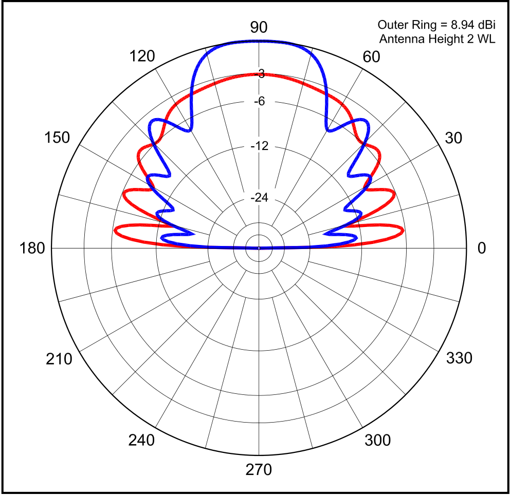
Figure 4—A comparison of elevation patterns for 2-element turnstiles (crossed 2-element Yagis, shown in blue) and a Moxon pair (shown in red), both at 2λ height.
| Dimension | 435.6 MHz
|
||
|---|---|---|---|
Figure 5—The basic dimensions of a Moxon rectangle. Two identical rectangles are required for each “turnstiled” pair.
|
|
|||
|---|---|---|---|---|
| 40 | August 2001 | |||
|
|
|---|
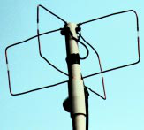
The 435-MHz Moxons.
You can contact the author at 1434 High Mesa Dr, Knoxville, TN 37938;cebik@ cebik.com.
August 2001 41


