

The demodulation data controlled the motors successfully
Study on a 5.8GHz Injection-locked Magnetron for Transferring Data
Bo Yang*+, Tomohiko Mitani*, Naoki Shinohara*
*Research Institute for Sustainable Humanosphere,
Kyoto University
Uji, Kyoto, Japan, 611-0011
+yang_bo@rish.kyoto-u.ac.jp

978-1-5386-5717-1/18/$31.00 ©2018 IEEE
injection signal stabilizes the magnetron oscillation frequency. A phase locked loop (PLL) method controlled the magnetron phase and the magnetrons worked in a low noise level [3]-[6]. The injection-locked magnetron was applied in a wide area, like wireless power transfer [3]-[4], power combining [5], and communication [6].
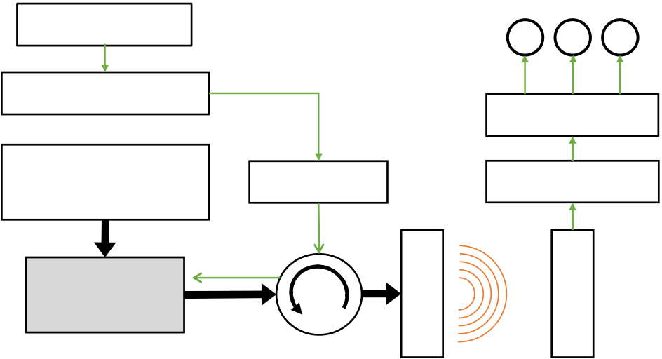
Figure 2 shows a block diagram of the injection-locked magnetron for the FSK modulation system. A LabVIEW program was designed and output the motor control signal to the modulator (Pakite PAT-630 transmitter) through the RS-232 TxD port. The modulator modulated the control signal on the microwave by FSK. This FSK modulated signal was amplified to 10 W and via a circulator, injected to the magnetron (Panasonic M5802). Here, the modulation frequency was nearly at the magnetron oscillation frequency. Then, the magnetron followed the modulated signal and amplified it. Then the high-power modulated microwaves were transmitted through the antenna. At the receiver, the transmitted microwaves were received and demodulated by a frequency demodulator (Pakite PAT-630 receiver). Then a

| PC LabVIEW | M | M | ||
|---|---|---|---|---|
| RS232 | Driver circuit | |||
| Modulator | ||||
| High-Voltage | Demodulator | |||
| Power Supply | ||||
Circulator
Fig.1 Schematic of data transfer system by FSK modulation
|
|
|---|---|
|
|
| 5.774 GHz-5.776 GHz | |
|
|
|
We demonstrated a 5.8 GHz injection-locked magnetron could transmit the motor control data by FSK modulation. Through the transmitted data, we successfully controlled the electric trolley. In the future, we will build a wireless power and data transfer system for the electric trolley.
ACKNOWLEDGMENT
| program: | Microwave | Energy | Transmission |
|---|
[1] S. Schneider, F. Hegger, N. Hochgeschwender, R. Dwiputra, A. Mori- arty, J. Berghofer, G. K. Kraetzschmar, "Design and development of a benchmarking testbed for the Factory of the Future", 2015 IEEE 20th
| RS-232 TxD signal [V] | 2.5 | 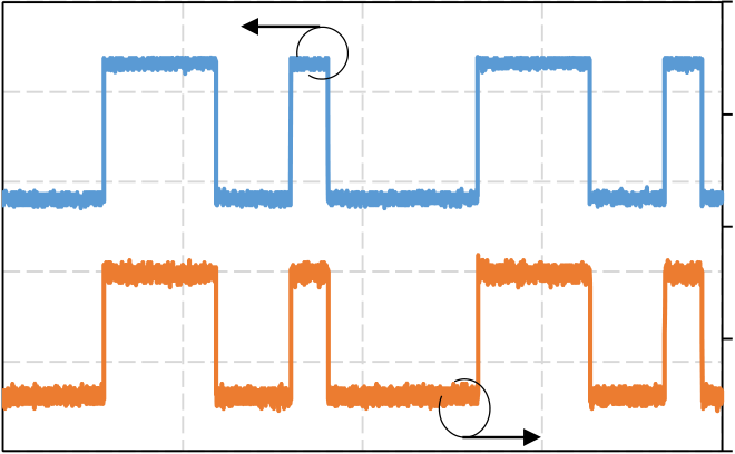 |
2.8 | RS-232 RxD signal [V] | [2] |
|
||||||||||||
|---|---|---|---|---|---|---|---|---|---|---|---|---|---|---|---|---|---|---|
| 1.5 | ||||||||||||||||||
| 2.3 | ||||||||||||||||||
| 0.5 | 1.8 | [3] | ||||||||||||||||
| GHz | Power-Variable | Phase-Controlled | Magnetron ” , | IEICE | ||||||||||||||
| -0.5 | 1.3 | [4] |
|
|||||||||||||||
|
||||||||||||||||||
| -1.5 | ||||||||||||||||||
| -2.5 | 0.8 | [5] | ||||||||||||||||
| 0 | 0.5 | 1 | 1.5 | 2 | [6] | |||||||||||||
|
||||||||||||||||||
| Time [ms] | ||||||||||||||||||
|
||||||||||||||||||
| Performance | of | an | Injection-Locked | CW | Magnetron,” | |||||||||||||
| Transactions on Electron Devices, vol. 53, No. 7, pp. 1721-1729, 2006 | ||||||||||||||||||


