

Table of Contents
INTRODUCTION
This project is work on design of arithmetic logical unit. I have used mulitsim software to create a 4 opcode. In the Alu operation based on add, subtract, multiplication and division. Then implement a logic operation with the help of adder. The output of these circuits largely depends on the levels present at the input terminals at any given time, for example. No memory is present in this circuit. The current state of this circuit is unaffected by the previous state of the input. A combinational circuit has "n" number of inputs and "m" number of outputs. Half-adder and full adder, subtractor, encoder, decoder, multiplexer, and demultiplexer are a few examples of combinational circuits. In this article, a summary of half adders and full adders and how they interact with truth tables are covered. An arithmetic logic unit (ALU) is a combinational logic circuit that can operate on integer binary values in a variety of arithmetic and bitwise logical ways. The basic building component of numerous computing circuits, such as Central Processing Elements, is the ALU (CPUs).
DESIGN
Used component to design Alu operations
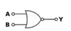
Xnor - The complement (reverse) of the Exclusive-OR logic is the Exclusive-NOR logic. Exclusive-OR and NOT gates are combined in a serial fashion to create it. The sentence "Both & B, not A or B" is the output of the Exclusive-NOR gate. When both inputs "A" and "B," i.e., both "HIGH" or "LOW," are at the same logic level, the Exclusive-NOR gate's outputs is said to be "HIGH." The Exclusive-NOR gate's output will be "LOW" in the case of either "A" or "B," which are "01" or "10." The Exclusive-NOR gate, also known as a "Equivalence Gate," only produces the logic "HIGH" when both of its input are equal.
Diagram of nor gate
| Truth table of xnor gate | ||
|---|---|---|
| a | b | Q |
| 0 | 0 | 1 |
| 0 | 1 | 0 |
| 1 | 0 | 0 |
| 1 | 1 | 1 |
Table
| a | b | c |
|---|---|---|
| 0 | 0 | 1 |
| 0 | 1 | 1 |
| 1 | 0 | 1 |
| 1 | 1 | 0 |
Full adder -
The adder known as a "full adder" adds three inputs and generates two outputs. A and B make up the first two inputs, and C-IN is the third input. The normal output is denoted as S, which represents SUM, while the output carry is designated as C-OUT. Eight inputs can be used to form a byte-wide adder using full adder logic, and the carry bit can be cascaded from one adder to the next. We employ a full adder since a 1-bit half-adder cannot use a carry-in bit when one is accessible, therefore we must use another 1-bit adder. Three operands are added via a 1-bit complete adder, which produces 2-bit results.
Multiplixer – it is combinational circuit delivering one or more analogue or digital signals over a single transmission system at various rates of speed is known as multiplexing, as well as the multiplexer is the tool that we employ to carry it out.
The multiplexer, often known as a "MUX" or "MPX," is a combinational logic circuit that enables the application of a control signal to switch one of numerous input lines through to a single common output line. Multiplexers connect or regulate numerous input lines known as "channels" one at a time towards the out in a manner similar to that of highly quick acting regard to job rotary valves.
Methodology
Truth Table of analysis result
.


