

Split ring resonator based left handed coplanar waveguide
Appl. Sci.2012, 2, 375-395; doi:10.3390/app2020375
OPEN ACCESS
applied sciences
ISSN 2076-3417
www.mdpi.com/journal/applsci* Author to whom correspondence should be addressed; E-Mail: Tel.: +34-93-581-35-22; Fax: +34-93-581-26-00.
Received: 15 March 2012 / Accepted: 10 April 2012 / Published: 20 April 2012
Appl. Sci.2012, 2 376
Transmission line resonators are also planar resonators, but their dimensions scale with the resonance frequency. It is well known, for instance, that a short-circuited λ/2 transmission line behaves as a series resonator, whereas it can be modeled by a parallel resonator if it is open ended [1]. Conversely, for λ/4 lines, a short-circuit load provides a parallel resonance, whereas for an open ended line the input impedance is that of a series resonator. Such transmission line resonators have been used in many microwave applications, such as filters (parallel coupled line bandpass filters, gap coupled λ/2-resonator filters, bandpass and bandstop filters based on shunt stubs, etc.) and antennas (printed dipole and monopole antennas, for instance) [1]. However, the fact that their dimensions scale with frequency is a limiting aspect in terms of device miniaturization.
Appl. Sci.2012, 2 377
length of the SISS is significantly smaller than the length of the transmission line stub, as corresponds to a semilumped component.
| (a) | (b) | (c) | (d) |
|---|
Appl. Sci.2012, 2 378
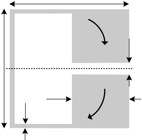
Figure 2. (a) λ/2ring resonator. (b) Split ring resonator (SRR). (c) First bulk SRR-based reported structure exhibiting backward wave propagation in a certain frequency band. Photograph courtesy of D.R. Smith.
| (a) | 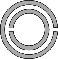 |
|
|---|---|---|
| (b) |
3.1. Topologies and Circuit Models of the Isolated Resonators
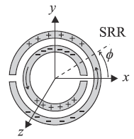
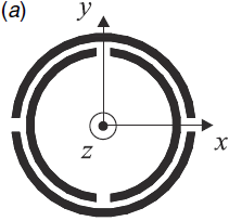
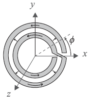
Let us begin with the SRR already considered in the previous section [12]. As long as the distance between both rings is small (i.e., there is significant coupling between them), the particle can be considered to be electrically small and a quasi-static analysis to infer the SRR inductance and capacitance can be applied. Such an analysis was carried out in [7,15]. When the SRR is excited by an external time-varying magnetic field directed along the SRR axis (z-axis in Figure 3), the cuts on each ring force the electric current to flow from one ring to another across the slot between them, taking the form of a strong displacement current. The slot between the rings therefore behaves as a distributed capacitance, and the whole SRR has the equivalent circuit shown in Figure 3(b), where Ls is the SRR self-inductance and Co/2 is the capacitance associated with each SRR half. This capacitance is Co = 2πroCpul, where ro is the mean radius of the SRR, and Cpul is the per unit length capacitance along the slot between the rings. The total capacitance of this circuit is the series connection of the capacitance of both SRR halves, that is, Co/4. Therefore, the resonance frequency ωo is given by:
| ωo | = | 2 | o | = | 2 | (1) | |
|---|---|---|---|---|---|---|---|
| LC s |
Appl. Sci.2012, 2 379
A more detailed circuit model, which takes into account the gap capacitance and includes a transmission line model for the slot between the rings has been reported in [18], but such a model converges to the model of Figure 3 when the capacitance of the cuts is neglected and the electrical length of the SRR is small [18]. As both approximations are usually fulfilled for any practical SRR design, the more simple model reported above is assumed valid in this paper.
An alternative way to obtain inversion symmetry, thus overcoming bianisotropy is by introducing additional cuts in the edge coupled SRR, as Figure 4(d) illustrates [19]. This particle, called double slit split ring resonator DS-SRR, exhibits the same inductance as the SRR, but its capacitance is four times smaller since it is the result of the series connected edge capacitances of each SRR quarter. This means


| (a) | (b) |
(c) | ||
|---|---|---|---|---|
| (b) | l2 | l1 | |||
|---|---|---|---|---|---|
| + + + + S | |||||
|
(d) | ||||
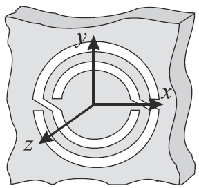
Let us now consider the application of duality to some of the previous particles. If the topology of the SRR is removed from a metallic film, the resulting particle (Figure 6) can be considered the negative image, or the complementary counterpart, of the SRR. For this reason, this particle has been called complementary split ring resonator (CSRR) [25]. It can be easily demonstrated by applying the Babinet principle, that the CSRR can be excited by means of an axial time varying electric field or by means of a magnetic field applied to the plane of the particle [26]. Under ideal conditions, i.e., a perfectly conducting and zero-thickness metallic screen, it can be demonstrated that the resonance frequency of the CSRR is identical to the resonance frequency of the SRR (provided identical dimensions and substrate are considered). Indeed, the capacitance of the CSRR, Cc, is the capacitance of a disk of radius ro−c/2 surrounded by a ground plane at a distance c of its edge. The inductance is given by the parallel connection of the two inductances of the metallic strips connecting the inner and outer metallic regions of the CSRR. These inductive values are given by Lo/2, where Lo = 2πrLpul, with Lpul being the per unit length inductance of the CPWs connecting the inner disk to ground.
Figure 6. Complementary split ring resonator (CSRR) topology and its equivalent circuit model. Geometrical parameters of the CSRR are identical to those of Figure 3 referred to
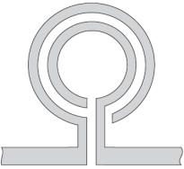
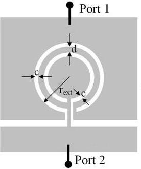
Complementarity can also be applied to the NB-SRR, DS-SRR, 2-SR, SIR and OSRR. Let us consider in certain detail the complementary counterparts of the SIR and OSRR, since they are of special interest for microwave and metamaterial-based circuit design. The complementary version of the open split ring resonator was called open complementary split ring resonator (OCSRR) [27]. The OCSRR is the complementary (negative) image of the OSRR, but it can also be considered to be the open version of the CSRR. However, the OCSRR must be considered with some caution, since the metallic terminals of the OSRR disappear by applying duality. As shown in Figure 7(a), the OCSRR is an open particle with terminals for external connection (excitation) as indicated in the figure. From one terminal to the other there are two possible current paths: On one hand, the inductive path through the strip between the ring slots; on the other hand, the capacitive path through the slots. Therefore the OCSRR is an open parallel resonant tank. The capacitance of the particle is the capacitance of the CSRR, Cc; the inductance is four times larger than the inductance of the CSRR. This means that the OCSRR is smaller than the CSRR by a factor of two. Indeed, the resonance frequency and electrical size of the OSRR and the OCSRR are identical (provided the same dimensions and substrate are considered).
The complementary counterpart of the SIR has been called dumb-bell defected ground structure (DB-DGS). The reason is that this structure is dumb-bell shaped, and it is typically etched in the ground plane of microstrip lines, creating thus a defect, or pattern, in such a ground plane (Figure 7(b)). This structure behaves like a series connected parallel resonant tank, as reported in [28]. Thus, OCSRRs and DB-DGSs are of interest in applications where electrically small open parallel resonators are required.
 |
(b) |
|---|
3.2. Transmission Lines Loaded with Electrically Small Resonators
In microwave applications, rather than isolated, the resonators considered in the previous sub-section are coupled (or connected) to host transmission lines (microstrip lines, CPWs, etc.). Despite the fact that such electrically small particles can also be present in metallic waveguides, the main interest of this paper is planar technology. For this reason, the present section is devoted only to the study of planar transmission lines loaded with semilumped resonators.
| s | = | M C 2 | sωo 2 | 1 | + | 4 | L | p | 2 | |||||||||||||
|---|---|---|---|---|---|---|---|---|---|---|---|---|---|---|---|---|---|---|---|---|---|---|
| L | ' | 2 | L | (2) | ||||||||||||||||||
| 1 | + | M | ||||||||||||||||||||
| 2 | L L p | s | ||||||||||||||||||||
| 2 | L |
|
| 1 | + | 2 | M | 2 | s | |
||||||||||||
| C | ' | = | | L L p | (3) | |||||||||||||||||
| s | M | 2ωo 2 | | 1 | + | 4 | L | p | ||||||||||||||
| | L | |||||||||||||||||||||
| Appl. Sci.2012, 2 | L ' | = | | 2 | + | L | | L | − | L |
|
384 | ||||
|---|---|---|---|---|---|---|---|---|---|---|---|---|---|---|---|---|
| | 2 | L | p | | 2 | s | (4) | |||||||||
| L | ' | = | 2 | L | + | |||||||||||
| p | p | (5) | ||||||||||||||
| (a) |
|
|---|
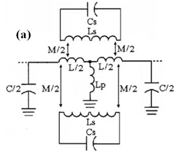
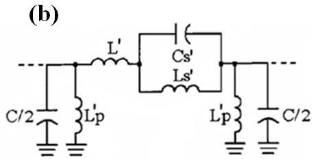
Figure 9. (a) Typical topology of a SRR- and strip-loaded CPW. (b) Equivalent circuit model of the unit cell. (c) Transformed circuit model.
| (a) | (c) |
|---|
| cosβ | =+ | Z | s | ( ) | |
|---|---|---|---|---|---|
| Z | p | (ω) | (6) |
| Z | B | (ω) | = | Z | s | ( ) | Z | p |
|
(7) | ||
|---|---|---|---|---|---|---|---|---|---|---|---|---|
| 1 | + | Z | s |
|
||||||||
| 2 | Z | p | ||||||||||
| Z | B | () | = | Z | s | ( )[ Z | s | ( ) | + | 2 Z | p |
|
(8) |
|---|
It has been mentioned before that the electrical size of the SRR can be decreased through different strategies. However, as discussed in [38], reducing the particle size has the effect of narrowing the bandwidth. Therefore, a trade-off between size and bandwidth when choosing the loading particles must be taken into account. This important aspect is illustrated in Figure 10, where the transmission coefficient of a CPW transmission line loaded with different resonant elements is depicted. If, for instance, a notch filter with much localized frequency is required, the use of a 2-SR spiral or a BC-2SR, rather than a SRR, is recommended. However, for applications of strip- and resonator-loaded CPW as bandpass filters, SRRs are necessary if the required bandwidth is moderate.
| Appl. Sci.2012, 2 | C | 2 C g | = 2 C s | + | C | par | ) | 386 | |||||
|---|---|---|---|---|---|---|---|---|---|---|---|---|---|
| (9) | |||||||||||||
| = | C | par | (2 C | s | + | C | par | ||||||
| C | (10) | ||||||||||||
where Cpar = Cf + CL. Like for the SRR-loaded CPW, CSRR loaded lines can be analyzed through their lumped element equivalent circuit, and expressions (6) and (8). The parameter extraction technique for these CSRR-loaded lines has been published in [40].
Figure 11. (a) Typical topology of a CSRR loaded microstrip line. (b) Equivalent circuit model of the unit cell.
| (a) |
|---|
| (b) | (c) |
|---|
The circuit models depicted in Figures 11 and 12 also apply for microstrip lines loaded with complementary spirals or with other complementary closed particles. Concerning the trade-off between particle size and bandwidth, the same comments in reference to SRR-loaded lines also apply (see [38] for more details and for numerical calculations).
The main relevant limitation of SRR- and CSRR-loaded lines is the narrow bandwidth, which is related to the limited coupling between the line and the resonator. In band pass structures, moderate and wide bands have been achieved by merging the backward and the forward wave transmission bands [41]. However, the validity of the models of the SRR- and CSRR-loaded lines in the forward wave transmission band is restricted to only a small portion of the band [42]. The DS-SRR (or DS-CSRR) has been considered in order to implement moderate or even wideband stop band structures, but this particle is electrically larger than the SRR (or CSRR), and therefore the accuracy of the circuit model to properly describe lines loaded with such particles is questionable. An alternative approach to implement wide band structures is the combined use of OSRRs and OCSRR in transmission lines.
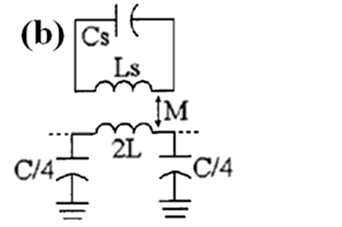
Figure 13. Layout (a), circuit model (b) and simplified circuit model (c) of a CPW transmission line loaded with a series connected open split ring resonator (L’s = Ls + 2L).
|
(c) |
|---|
(a)
| (b) | (c) |
|---|
Figure 15. Typical layout of a SIR-loaded CPW (a) and equivalent circuit model (b).
| (a) | (b) | L/2 |
|
|
|---|---|---|---|---|
In this section, three illustrative applications of some of the semilumped resonators considered before are highlighted. Rather than discussing them in detail, the main aim is to point out the key characteristics of the resonators for the considered applications.
4.1. Wideband Bandpass Filters and Dual-band Components based on OSRRs and OCSRRs
Appl. Sci.2012, 2 389
Figure 17. (a) Frequency response of the circuit of Figure 16. (b) Characteristic impedance. (c) Dispersion diagram. The element values of the circuit model are (in reference of Figure 13(c) and Figure 14(c)): L’s = 6.94 nH, Cs= 0.85 pF, C = 0.28 pF, L = 0.76 nH, L’p = 1.95 nH and C’p = 2.43 pF. From [43]; copyright 2009, IEEE; reprinted with permission.
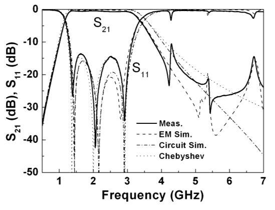
Figure 17 shows the frequency response, as well as the characteristic impedance and dispersion. Clearly, the structure exhibits a composite right/left handed behavior. It is interesting to mention that the equivalent circuit model of the structure (consisting of the cascade of the circuits shown in Figures 13 and 14 for each OSRR and OCSRR section) provides a good estimation of the characteristics of the artificial transmission line up to frequencies that extend beyond the allowed transmission band. If parasitics in the models of Figures 13 and 14 are removed, the equivalent circuit
Figure 19. Fabricated dual-band power divider and frequency response. (a) Top view. (b) Bottom view. (c) Power division (S21, S31) and matching (S11).The substrate is the RogersRO3010 with thickness h = 0.635 mm and dielectric constant εr = 10.2. Dimensions are: l = 9 mm, W = 4 mm, G = 0.74 mm. For the open complementary split ring resonator: rext = 0.9 mm, c = 0.2 mm, d = 0.2 mm. For the open split ring resonators: rext = 1.5 mm, c = 0.3 mm, d = 0.2 mm. The wide metallic strip in the back substrate side has been added in order to enhance the shunt capacitance of the open complementary split ring resonator stage, as required to achieve the electrical characteristics of the device.The circuit parameters, referred to the circuits of Figure 13(c) and 14(c) are: C = 0.2 pF, L = 0.25 nH, Cs = 0.66 pF, L’s = 3.74 nH, C’p = 2.99 pF and L’p = 0.83 nH. From [43]; copyright 2009, IEEE; reprinted with permission.
(c)
Appl. Sci.2012, 2 391
Figure 20. Layout (a), photograph (b), and frequency response (c) of the fabricated elliptic lowpass filter.Dimensions are: W = 5 mm, G = 0.55 mm, l = 6.6 mm, b = 2.42 mm, c = 2.7 mm. The strips of the meander lines are of 0.2 mm. The filter has been fabricated on the Rogers RO3010 substrate with measured dielectric constant εr= 11.2 and thickness h = 254 μm. The circuit simulation corresponds to an ideal elliptic filter with the following characteristics:order-3 elliptic-function LPF with a passband ripple of LAr = 0.1 dB, a cutoff frequency of fc= 1 GHz and a stopband attenuation of LAs = 30.52 dB with the equal-ripple stopband starting normalized frequency Ωs = 2.5. From [46], copyright 2010, IEEE; reprinted with permission.
| (b) | (c) |
|---|
4.3. Dual-band Antennas Based on SRs
It has been recently demonstrated that dual-band antennas with very closely spaced operating frequencies (such as those required, for instance, in UHF-RFID applications to cover different regulated bands worldwide), can be implemented by coupling electrically small resonators to mono-band antennas [47]. This perturbs the impedance of the antenna and conjugate impedance matching between the antenna and the integrated circuit at two required frequencies can be achieved. For this application, the key aspect is the resonator’s size. For this reason, the use of a 2-SR is of interest.
| (a) | lm | (b) | sh | lr | |||
|---|---|---|---|---|---|---|---|
| dl |
|
||||||
| df |
Appl. Sci.2012, 2 392
This work was supported by Spain-MICIIN (project contracts TEC2010-17512 METATRANSFER and CSD2008-00066). Thanks are also given to the Catalan Government for giving support through the project 2009SGR-421.
References
5. Caloz, C.; Itoh, T. Electromagnetic Metamaterials: Transmission Line Theory and Microwave Applications; John Wiley & Sons, Inc.: Hoboken, NJ, USA, 2006.
6. Engheta, N.; Ziolkowski, R.W. Metamaterials: Physics and Engineering Explorations; John Wiley & Sons, Inc.: Hoboken, NJ, USA, 2006.
Appl. Sci.2012, 2 393
11. Naqui, J.; Durán-Sindreu, M.; Bonache, J.; Martín, F. Implementation of shunt connected series resonators through stepped-impedance shunt stubs: Analysis and limitations. IET Microw. Antennas Propag.2011, 5, 1336–1342.
18. Shamonin, M.; Shamonina, E.; Kalinin, V.; Solymar, L. Resonant frequencies of a split-ring resonator: Analytical solutions and numerical simulations. Microw. Opt. Technol. Lett.2005, 44, 133–137.
19. Marqués, R.; Baena, J.D.; Martel, J.; Medina, F.; Falcone, F.; Sorolla, M.; Martín, F. Novel Small Resonant Electromagnetic Particles for Metamaterial and Filter Design. In Proceedings of the International Conference on Electromagnetics in Advanced Applications (ICEAA’03), Torino, Italy, 8–12 September 2003; pp. 439–442.
24. Martel, J.; Marqués, R.; Falcone, F.; Baena, J.D.; Medina, F.; Martín, F.; Sorolla, M. A new LC series element for compact band pass filter design. IEEE Microw. Wirel. Compon. Lett.2004. 14, 210–212.
25. Falcone, F.; Lopetegi, T.; Baena, J.D.; Marqués, R.; Martín, F.; Sorolla, M. Effective negative-epsilon stop-band microstrip lines based on complementary split ring resonators. IEEE Microw. Wirel. Compon. Lett.2004, 14, 280–282.
29. Bilotti, F.; Toscano, A.; Vegni, L. Design of spiral and multiple split-ring resonators for the realization of miniaturized metamaterial samples. IEEE Trans. Ant. Prop. 2007, 55, 2258–2267, 30. McVay, J.; Engheta, N.; Hoorfar, A. High-impedance metamaterial surfaces using Hilbert-curve inclusions. IEEE Microw. Wirel. Compon. Lett. 2004, 14, 130–132.
31. Crnojevic-Bengin, V.; Radonic, V.; Jokanovic, B. Fractal geometries of complementary split-ring resonators. IEEE Trans. Microwave Theory Tech. 2008, 56, 2312–2321.
36. Naqui, J.; Durán-Sindreu, M.; Fernández-Prieto, A.; Mesa, F.; Medina, F.; Martín, F.
Forward, backward, electroinductive and complex waves in transmission line metamaterials. IEEE Antennas and Wireless Propagation Letters, submitted.
42. Gil, I.; Bonache, J.; Gil, M.; García-García, J.; Martín, F. Left handed and right handed transmission properties of microstrip lines loaded with complementary split rings resonators. Microw. Opt. Technol. Lett.2006, 48, 2508–2511.


