

PLC Binary Simulation Program Homework Answers Needed
Your Question:
 Step By
Step Answers with Explanation
Step By
Step Answers with Explanation
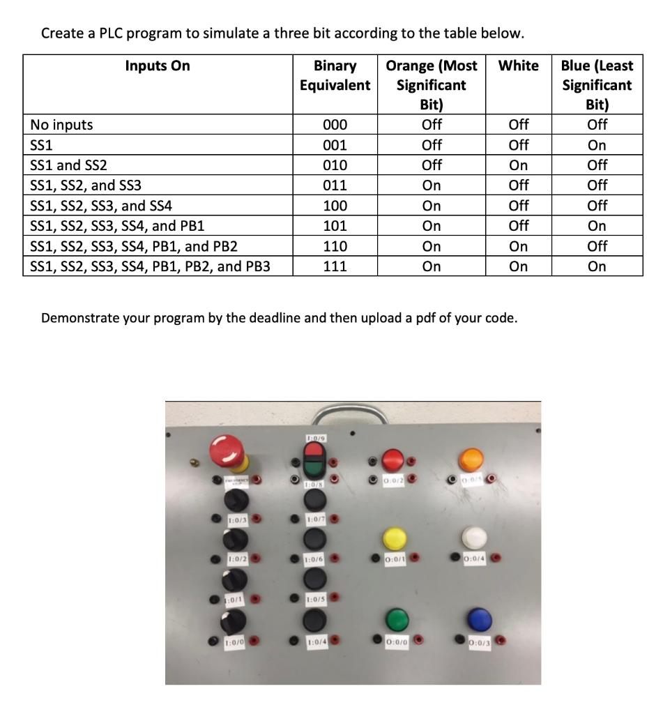
To create a PLC program to simulate a three-bit binary according to the given table, we'll use ladder logic programming. We'll use the specified input conditions and set the corresponding output bits. Here's a step-by-step explanation with a ladder diagram:
Step 1: Setting Up Inputs and Outputs
We'll create a ladder diagram to represent the logic required to achieve the binary outputs based on the input conditions:
```plaintext
PB1 ----[ ]----[ ]----[ ]----[ ]----[/]----[/]----[/]----[/]
PB2 ----[ ]----[ ]----[ ]----[ ]----[ ]----[/]----[/]----[/]
- Each input condition is represented by a normally open contact symbol `[ ]`, which signifies that the input is on.
- We've arranged the conditions according to the provided binary table, ensuring that when the specified inputs are on, the corresponding outputs will be energized.
To test the program, you can use a PLC simulator or an actual PLC if available. Input the specified conditions and observe the outputs to ensure they match the provided table.
Step 5: Documentation


