
First need find the impedance the circuit impedance the circuit given the sum the resistive
Solved Step by Step With Explanation- Power Analysis: Values and PF
Questions
Power Factor
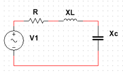
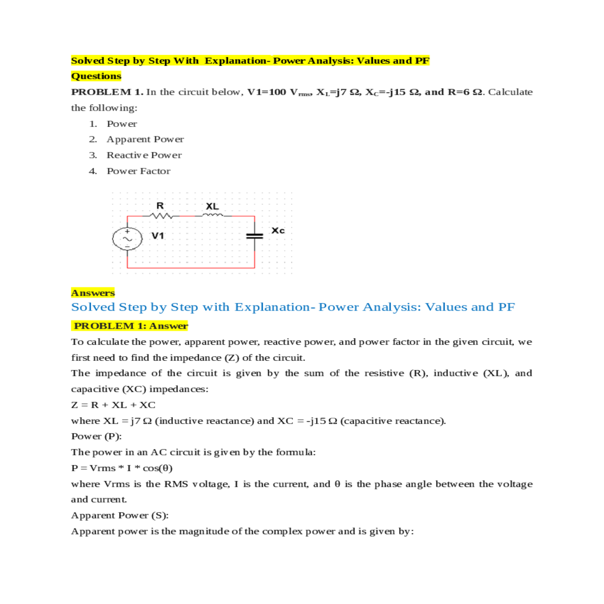
The impedance of the circuit is given by the sum of the resistive (R), inductive (XL), and capacitive (XC) impedances:
Z = R + XL + XC
where Vrms is the RMS voltage, I is the current, and θ is the phase angle between the voltage and current.
Apparent Power (S):
Q = Vrms * I * sin(θ)
Power Factor (PF):
Z = R + XL + XC
Z = 6 + j7 - j15
I = Vrms / Z
I = 100 / (6 + j22)
P ≈ 100 * 4.347 * cos(θ) [Neglecting the imaginary component for real power]
P ≈ 434.7 * cos(θ)
Step 5: Calculate the reactive power (Q):
Q = Vrms * I * sin(θ)
PF = P / S
PF ≈ (434.7 * cos(θ)) / (434.7 - j1565.2)
θ ≈ arccos(114.304 / 0.263) [In radians]
Power (P) is approximately 434.7 * cos(θ) W


