

Figure transformer based test balun schematic
A Comparison of Two Power Combining Elements for LWA Active-Baluns - 180° Hybrid versus Wideband Transformer
Brian Hicks, Nagini Paravastu , Paul Ray, and Bill Erickson May 9, 2007
Figure 1 – Baseline Balun Structure
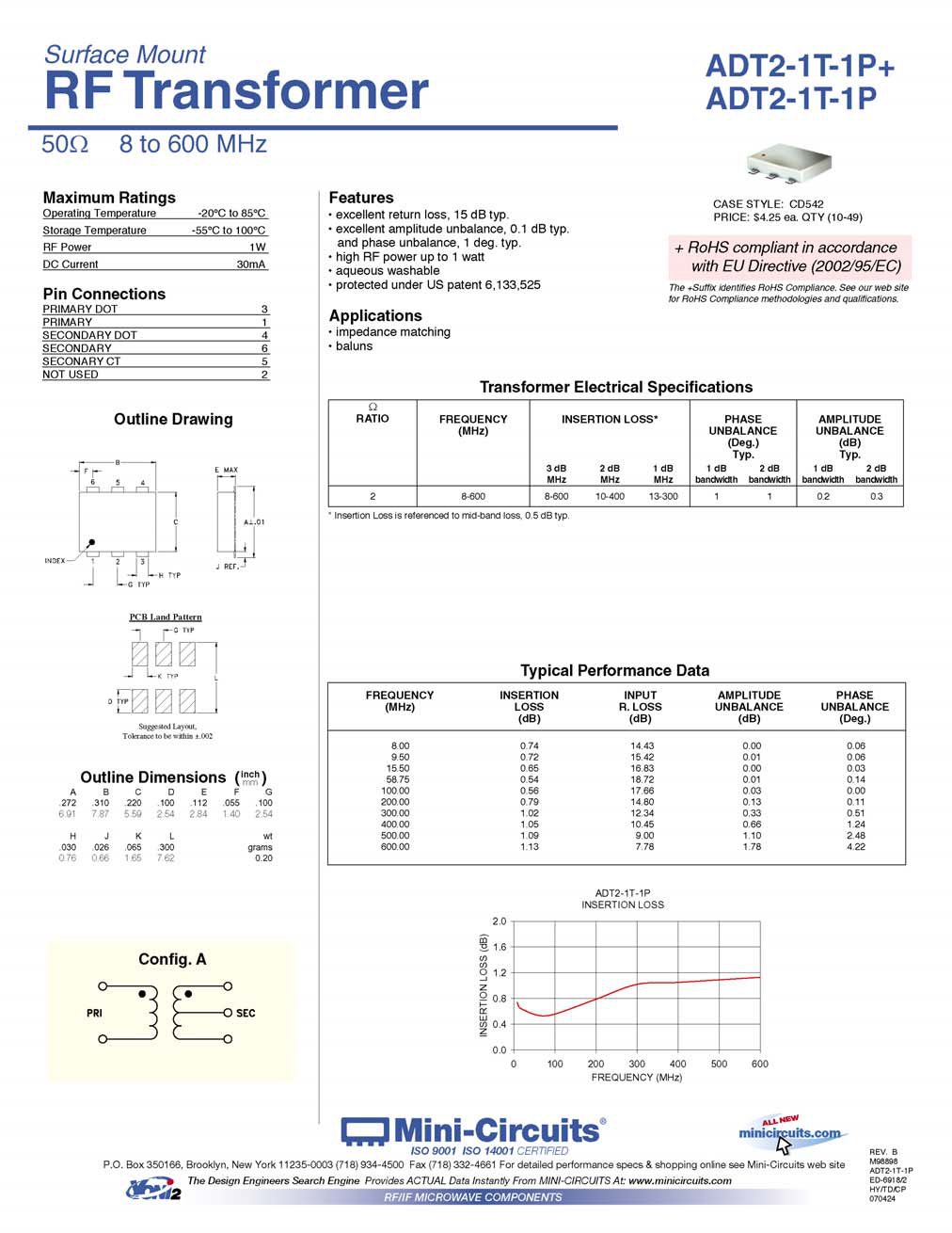
Despite these desirable characteristics, the cost of a 180° hybrid is typically greater than an RF transformer, such as the MiniCircuits ADT2-2-1T-1P used on the Experimental Test Array (ETA) [1]. A detailed performance and cost comparison of the two options has therefore been undertaken to determine which element would be the preferable choice for the LWA active baluns.
Figure 2 – Single Polarization Test Baluns
III. Performance Data
The hybrid version of the balun is shown to deliver close to the 100 Ω (2 x 50Ω) impedance at the antenna feedpoint as required by the baseline antenna design solidly across the entire LWA band (Figures 8, 9). The transformer version of the balun delivers a feedpoint impedance of approximately 50Ω (2 x 25Ω) across the LWA band.
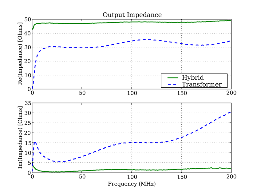
Similarly, the output impedance of the hybrid based balun was found to be flat at ~50 Ω across the entire LWA band with a negligible imaginary component. The transformer based unit presented frequency variant output impedance that ranged from 30 to 40Ω with a significant (and varying) imaginary component.
Figure 3
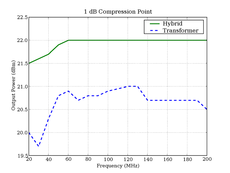
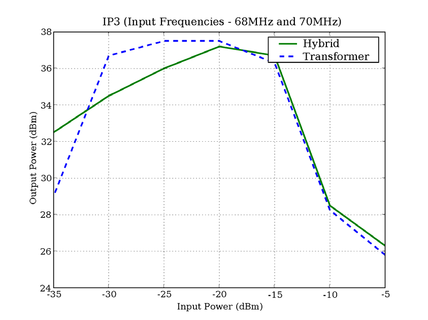
Figure 6
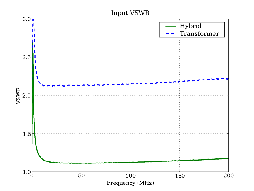
Figure 8
Figure 10
V. Summary and Recommendations
We have presented a performance comparison of two candidate power combining elements for the LWA active balun – the 180° hybrid made by Tele-Tech, and the wideband transformer made by Minicircuits. Two single polarization active baluns were fabricated that were identical in circuit configuration and layout with the exception that one used the 180° hybrid and the other used the transformer as the power combining element. Gain, noise figure, intermodulation distortion, 1 dB compression point, and input and output VSWR were measured on each balun using the same test equipment. The two baluns performed comparably (with the hybrid-based balun being slightly superior) in every area except input and output VSWR. While the hybrid-based balun had input and output VSWR’s corresponding to a ~50Ω impedance, the transformer-based balun had input and output VSWR’s corresponding to impedances ranging from 25Ω - 40Ω. The transformer-based balun therefore presents a less effective impedance match to the LWA baseline big blade antenna, as well as to 50Ω coaxial RF cable. The standard Tele-Tech hybrid (HX62A) provides a good impedance match to 50Ω coaxial cable, and a version with 75Ω output impedance is available at no additional cost should the LWA project decide to use 75Ω cable.
Figure 12 - IMD Measurement Setup
10
2.HP E4422B Signal Generator
3.HP 8561B Spectrum Analyzer
11
VIII. Test Balun Schematics
a. Figure 14 -Transformer Based Test Balun Schematic
13
IX. References
[1] “Active Balun Schematic/Parts List”, Steve Ellingson, October 9, 2005 http://www.ece.vt.edu/swe/eta/AB/ETA_AB_051026.pdf
16


