
Draw the schematic diagram and write all necessary assumptions
b. Neglecting the contact resistance, construct the thermal circuits for all three materials.
c. Calculate the heat generation in material B, qe
Solved Step by step with explanation Calculate the heat generation in material B, qe.
```
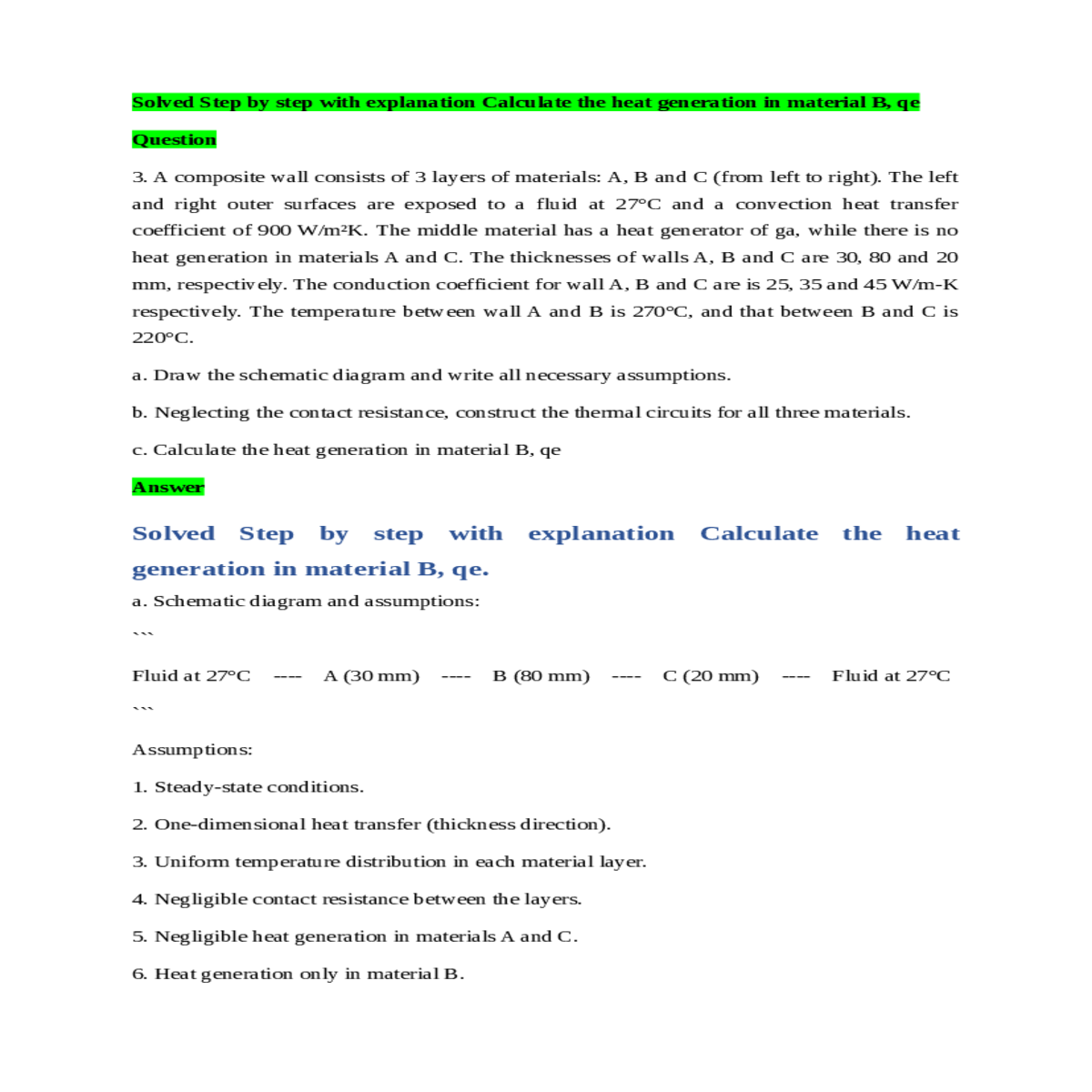
Assumptions:
5. Negligible heat generation in materials A and C.
6. Heat generation only in material B.
R_conv R1 (A) R2 (B) R3 (C)
| | | |
q = (T1 - T2) / (R1 + R2 + R3)
where q is the heat generation, T1 is the temperature on one side of the material (270°C), T2 is the temperature on the other side of the material (220°C), and R1, R2, and R3 are the thermal resistances of materials A, B, and C, respectively.
R2 = thickness of B / (conduction coefficient of B * area) = 0.08 m / (35 W/m-K * 1 m²) = 0.0023 K/W
R3 = thickness of C / (conduction coefficient of C * area) = 0.02 m / (45 W/m-K * 1 m²) = 0.0009 K/W
Therefore, the heat generation in material B (qe) is 11,363.64 W.


