
Draw the resulting output waveform for the circuit fig
| PROBLEMS | § |
|---|
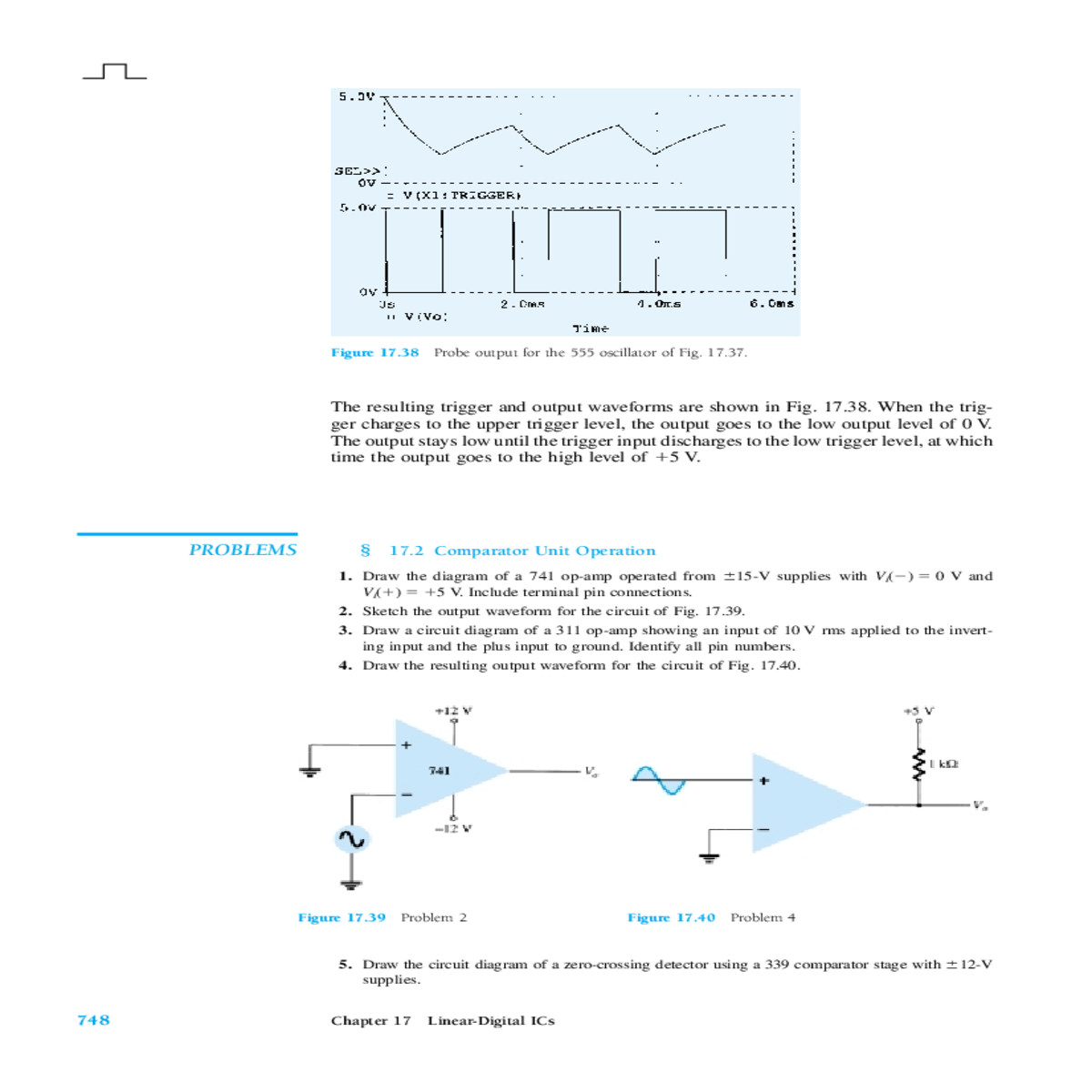
2. Sketch the output waveform for the circuit of Fig. 17.39.
3. Draw a circuit diagram of a 311 op-amp showing an input of 10 V rms applied to the invert- ing input and the plus input to ground. Identify all pin numbers.
| Figure 17.39 | Figure 17.40 |
|
|---|
5. Draw the circuit diagram of a zero-crossing detector using a 339 comparator stage with �12-V
| Chapter 17 |
|---|
6. Sketch the output waveform for the circuit of Fig. 17.41.
| Figure 17.42 |
|---|
§ 17.3 Digital–Analog Converters
8. Sketch a five-stage ladder network using 15-k� and 30-k� resistors.


