

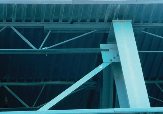
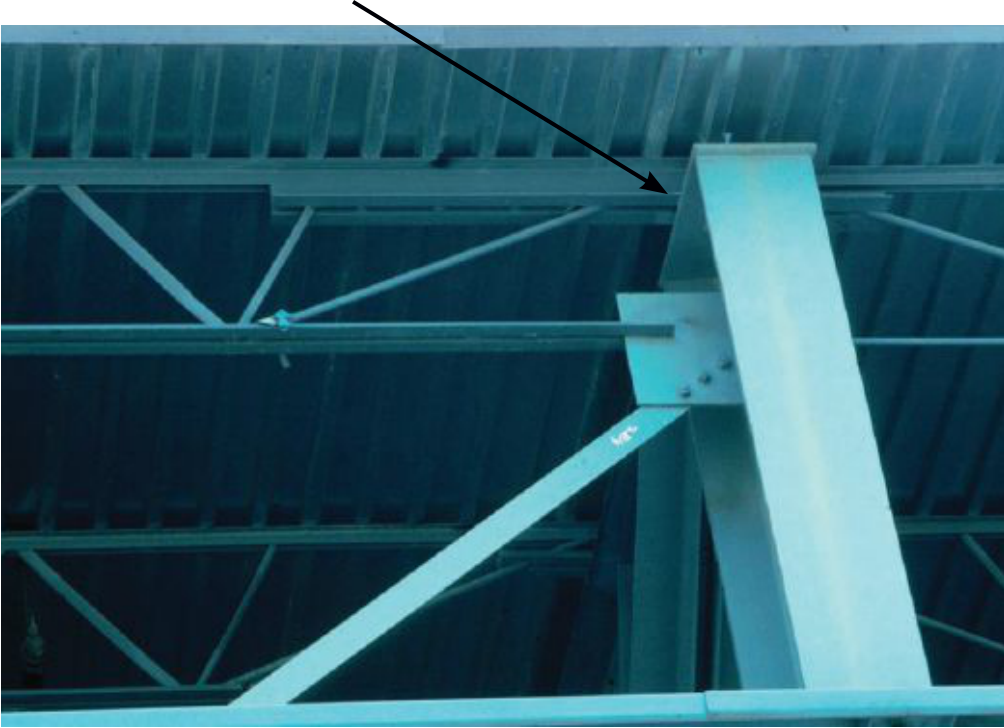
Dlh- series and joista typical vertical brace using joist girders
|
|---|
|
|---|
Free drainage. All roofs should be designed and built so that water is not retained on the roof surface. Even in roofs that are constructed with ¼ in. per ft slope, there are instances where free drainage may not occur. A classic example is a roof with no interior drains that drains to an eave gutter. This situation occurs when the first upslope joist or purlin deflects under snow load more than the eave member deflects. Often, the eave member does not deflect as it is supported by the building siding. A check can be made by the specifying professional for ponding stability using the Steel Joist Institute’s (SJI) Roof Bay Analysis Tool (read on for more on that tool).
Bay size. The designer may or may not have the opportunity to select the bay size for a proposed project. Owner requirements and functional requirements often dictate a certain bay size. In addition, the building footprint, which is often dictated
conference preview
Serviceability. The design of the lateral load envelope (i.e., the roof bracing and wall support system) must provide for the code-imposed loads, which establish the required strength of the structure. A second category of criteria establishes the serviceabil-ity limits of the design. These limits are rarely codified and are often selectively applied project by project based on the experience of the parties involved.
In AISC Design Guide 3: Serviceability Design Considerations for Steel Buildings (aisc.org/dg) several criteria are given for the con-trol of building drift and wall deflection. These criteria, when used, should be presented to the building owner as they help establish the quality of the completed building.
the least weight or the least cost bay size. Cost data can be input by
the user along with other design data. Bays can be evaluated using either ASD or LRFD. In addition, the bay can be evaluated for roof ponding stability, using an iterative analysis. Pull-down menus allow for easy selection of steel deck, joist (K, LH, DLH- Series) and joist
the top and bottom, thus square hollow structural section (HSS)
columns are often desirable due to their equal stiffness about
both principal axes. Difficult connections with HSS members
can be eliminated in single-story frames by placing the joists
and joist girders over the tops of the HSS. Other advantages of
HSS columns include the fact that they require less paint than
equivalent W-shapes and are aesthetically pleasing. W-shapes
may be more economical than HSS for exterior columns for the
following reasons:
• The wall system (girts) may be used to brace the weak axis of
the column.
• Bending moments due to wind loads are predominant about
one axis.
Fig. 1. Force transfer using top plate.
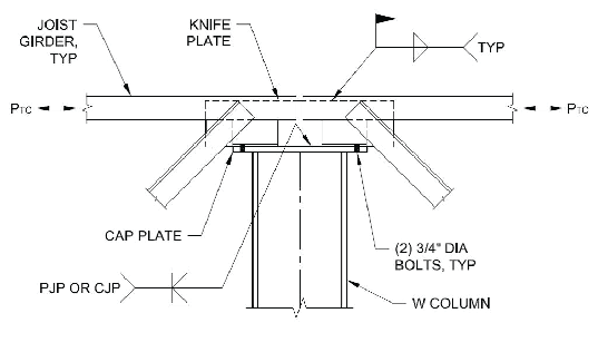
4 See framing plan for additional loads to be included in joist girder design, including mechanical loads.
5 See framing plan for joist spacing along girder.
• Braced frames may require bracing in both walls and roof. Bracing frequently interferes with plant operations and future expansion. If either consideration is important, ordinary moment frames may be the answer.
• The bracing of a roof system can be accomplished through X-bracing or a roof diaphragm. In either case the roof becomes analytically a large horizontal beam spanning between the walls or bracing which must transmit the lateral loads to the founda- tions. For large span-to-width ratios (greater than 3:1) the brac- ing requirements become excessive. A building with dimensions of 100 ft by 300 ft with potential future expansion in the long direction may best be suited for moment frames to minimize or eliminate bracing, which would interfere with future changes. • Consideration must be given to future expansion and/or modi- fication, where columns are either moved or eliminated. Such changes can generally be accomplished with greater ease where simple-span conditions exist.
34| MARCH 2020

|
||||||||||||||||||||||||
|
|
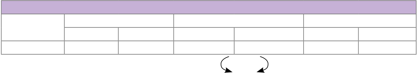
Wind Moment 1.0W | ||||||||||||||||||||||
| Number | Left | Right | Left | Right | Left | Right | ||||||||||||||||||
| G1 | – | – | ±105 | ±105 | ±120 | ±120 | ||||||||||||||||||
Modern Steel Construction |35
WWW.AUTOMATEDLAYOUT.COM
603-402-3055


