

Digital control oscillator using varactor and dac
| 52 |
|
Continuous-Time | M.H. Perrott | ||||
|---|---|---|---|---|---|---|---|
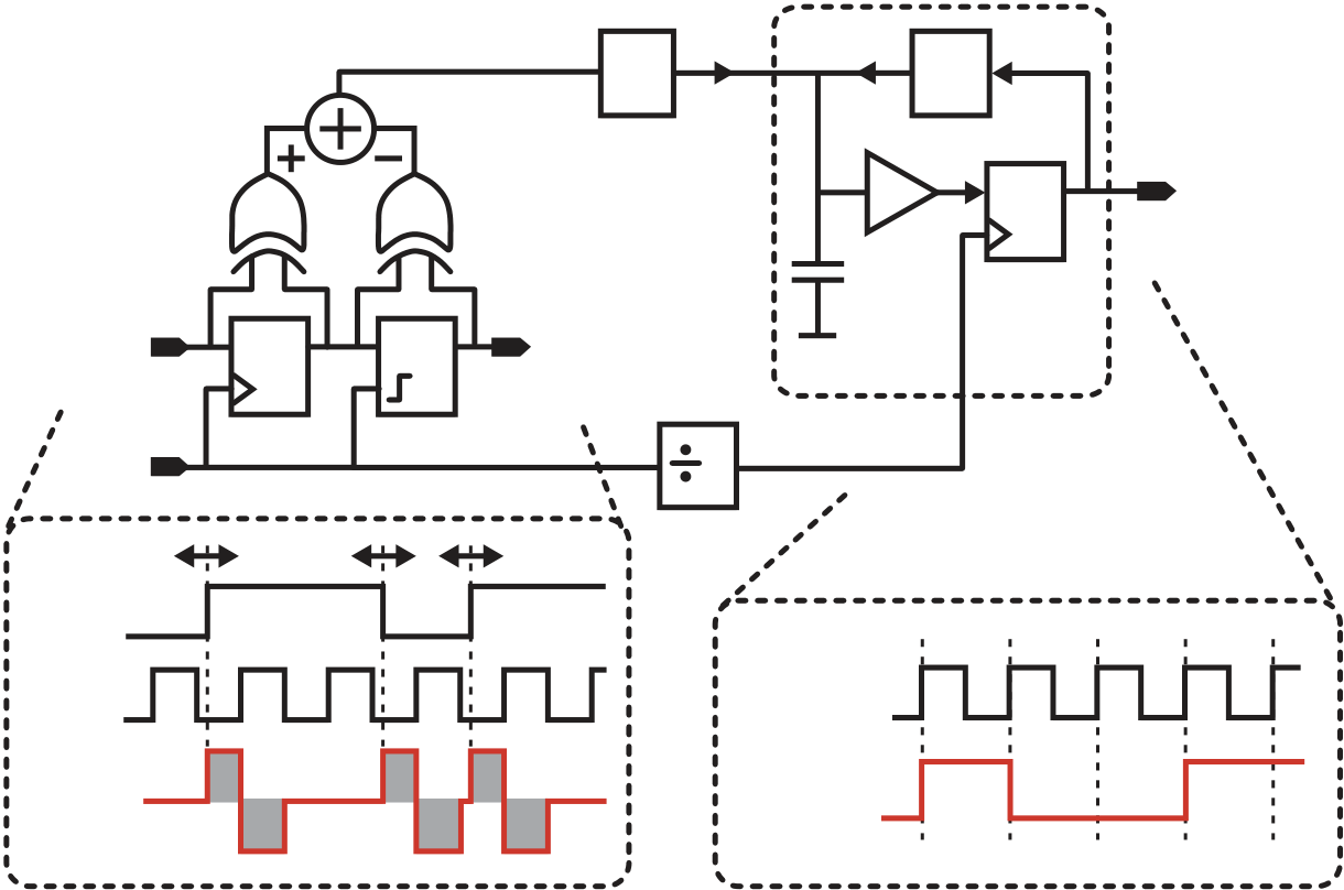
| Ipd | 2 | First Order Σ Δ ADC | |||||
| - Isd | |||||||
| D Q | D Q | retimed data(t) | |||||
| D Q | |||||||
| Cint | |||||||
| clk(t) | clk/2(t) | ||||||
| Reg | Latch | ||||||
data(t)
|
|---|
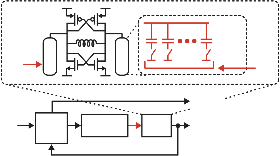
LC oscillator can be achieved through a switched-capacitor network by altering the
resonant frequency of the tank according to the amount of capacitance switched
| data(t) | Phase-to- Digital |
|
|---|
Fig. 7 Digital control of an LC oscillator using a switched-capacitor network
Figure 8 shows an alternative means of achieving digital control of an LC oscilla-tor, which is to simply control the input of a varactor within a hybrid VCO [7] with the output of a digital-to-analog converter (DAC). In order to limit the frequency range required of the varactor (which lowers its influence on the phase noise of the oscillator), a switched-capacitor network can be used to perform coarse calibration of the oscillator in order to remove the impact of process variations [7]. Since the unit capacitor size in the array can be much larger than the “all-digital” design shown in Fig. 7, its control network is much less complex and a simpler design effort can be applied to achieve high performance. In practice, the coarse calibration is often performed off-line with a frequency acquisition circuit, and the analog varactor is controlled by the feedback action of the phase-locked loop.
|
|---|
| data(t) | Phase-to- Digital |
|
|
||
|---|---|---|---|---|---|


