

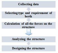
Design jetty decks for extreme vertical wave loads
ABSTRACT
Jetties are usually placed at the mouth of a river or entrance to a
body to
aid in- deepening and stabilizing of a channel for the benefit of
navigation. Properly
located jetties will confine the discharge area promote scour and extend
into
deep water the factor the place the modern-day slackens and
transported material lS deposited. Jetties also guard the ship channel
from waves and cross-currents and from long shore sand movements.
(1) Random stone: A rubble-mound shape is in truth a long mound of
random
stone. The large pieces are positioned on the outer face to come up with
the money for protection from destructive waves, and the smaller sized
stones are positioned in the interior of the structure. This type is
adaptable to any depth, may be placed on any variety of
bottoms and absorbs the wave energy with little reflected wave action.
This type
requires enormously giant amounts of material.
If not carried high enough, storm
waves may additionally sweep totally over the jetty and reason a
secondary wave motion in the
protected area, and if the voids between the stone are too giant a
considerable
portion of the wave electricity may skip via the structure.
(2) Stone and concrete kind is a mixture of rubble stone and
concrete.
This kind tiers from a rubble-mound structure, in which the voids in the
upper
portion of the rubble are filled with concrete, to large concrete
superstructure
on rubble-mound substructure. The mound is used either as
a foundation for a excessive concrete superstructure or as
the important structure surmounted by way of a concrete cap with
vertical, stepped, or inclined face. This type requires much
less material, and is
used where the foundation is tender or problem to scour. The
superstructure might also be
undermined by wave throwback down the face; rubble foundations require
time to become
permanently stable and ought to be placed years before the
superstructure:-This type of Jetty, when true designed and
constructed, gives very satisfactory service.
WAY OF SELECTION TO CONSTRUCT BERTHING STRUCTURES
Type of berthing structure and
utilized fabric for building depend on a range of factors
Local customs and practice: for suppose, Europe used the massive quays,
whereas, America used the open and light structures.
Material availability
The dedication of number of berths relies upon on dealing
with of site visitors in port .the planning of a new terminal
was influenced via preliminary investment.
The approximate members of the family used for the willpower of the
required range of berths are:
N1= W/ R* H * D
Where,
N1= crucial amount of berths for a sure cargo.
W = every year amount of this cargo imported and exported
(T/year).
R = coping with price of this cargo on the berth. (T/ hour) H
= quantity of working hours perday. (Hour/ day)
D = amount of working days per year. (Day/ year)
N1 is calculated for every type of cargo, and the overall number of
berths in the port N for all kinds of cargo is:
N = N1 + N2 + N3 +……..
DRAFT MAINTENANCE ALONG THE BERTH
The third era holder vessels have a draft of 12.5 m. Subsequently a depth of 13.5 m need to be stored up shut with the aid of the quay amid all conditions permitting adequate depth for exceptional remittances. Depth at the compartment ought to be 10% in abundance of most extreme stacked draft of configuration vessel to consider silting and vertical movement.
Deck elevation is fine-tuned at or above the easiest high spring dihydrogen monoxide level plus half the wave height close to the berth plus a free board of 1m. The most distance of quay area inclusive of fine-tuned fenders from the outer track of the crane is about 2.65m.
TURNING CIRCLE
The sector wished for ability of holder internal the terminal relies on upon the accompanying elements
Throughput predicted that will skip via the terminal for each and every annum.
Ratio of working slots: All the slots gave on the floor can not be handy for stacking due to the fact of different reasons. The diploma of working areas to regularly occurring apertures is normally taken as 0.8.
All useless masses of and on structures identifying with docks and
harbor ought to be evaluated and included in the graph configuration.
Dead hundreds comprise of the weight of all components of
the structure and additionally the weight of all permanent connections.
The DL of a port associated marine shape constitutes a relative
little price of the complete burden appearing up on the structure.
Wearing coat (Apron) = 0.20 X 25 = 5 kN/m2(density of the concrete is
taken 25 kN/m3)
Slab weight = 0.30 X 25 = 7.55 kN/m2
Beams
Transverse beams = 1.10 X 1.80 X25 = 50kN/m
Longitudinal beam = 1.10 X 0.60 X 25 =16.5 kN/m
Pile =1.70X21.65X25=920.12 kN/m
MOORING LOAD
Aw = wind age region in m2
P = wind age pressure in m2 to be taken as per IS: 875-1964
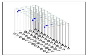
Real this is the unmistakable system yet port architects proposed that bollard pull =900kN is embraced (Plan load) By and large securing burden act in different edge of powers so we need to determine on the securing point while planning the billet. What's more, dispersing taken as bollard to bollard is 15m c/c ,in the event that guess we fixed 7 bollards, at that point the load on every bollard is 900/7 =F =128kN
Settling of powers on securing focuses are
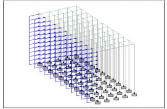
Fig.4 current load representation
F = 0.035kN/m2 For 1 unit of billet F = 0.035X33X21.65 =25kN .25kN for 12 heaps for each heap F = 2.02 kN
Burden circulation is changed over as uniform on heap F= 2.02/21.65 =0.096KN/m
k 1= likelihood factor (Hazard coefficient) K2= landscape, tallness and structure size factor K3= geology factor
Vz = (50)(0.92)(1.05)(1) =48.3m/sec
By virtue of waterfront structures with decorate, the weight made by qualification in water level at the fill side and waterside must be considered in plan arrangement. The extent of hydrostatic weight is influenced by the tidal degree, free water fluctuations, the ground water storm, the permeability of the foundation of establishment soil and the structure and furthermore the capability of available top off waste
BASIC LOAD COMBINATIONS
1.5DL+1.5LL+1(EARTHPRESSURE)+1(HYDROSTATICPRESSURE)+1.5(BERTHING LOAD)+1.5(MOORING Burden)
DESIGN OF Bar
TRANSVERSE Bar
Separating between bars:238mm
Cover:50mm
Dividing between bars:125mm
Cover:50mm
Successful depth:217mm
Successful cover:75mm
Evaluation of steel:Fe415
Dia of the pile:1700mm
CONCLUSION
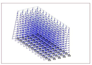
Various variables are to be considered while breaking down and planning the berthing structure. Horizontal stacks on the berthing structures are more prominent than those ashore based structures. Harmonious natural information, traffic guaging and soil information should be gotten from the proposed site area, run of the mill load dispersion is actuated on the shore line structures, so need to use STAAD Ace programming for the investigation what's more, structure. The structure was dissected and planned fulfilling different stacking conditions and measurement examination for efficient viewpoint was also dealt with without surpassing the auxiliary wellbeing. Up to going for planning or arranging a berthing structure, all the present and future hopeful conditions in regards to traffic information, hinterland extension and industrialization of that specific hinterland are to be examined, which also assume a significant job in molding the venture beginning at the primary spot.
Overbeek, J. and Klabbers, I.M., 2001. Design of jetty decks for extreme vertical wave loads. In Ports' 01: America's Ports: Gateway to the Global Economy (pp. 1-10).
Magnuson, N.C., 1967. Planning and Design of a Low-Weir Section Jetty (Coastal Engineering Conference in Santa Barbara, California, October 1965). Journal of the Waterways and Harbors Division, 93(2), pp.27-40.


