

Dargestellt der sql-ahnlichen esper event pattern language

Inhaltsverzeichnis: Tag 1
Session 2
Verteilte Abfragebearbeitung von Sensordaten . . . . . . . . . . . . . . . . . . . . . . . . . . . . . . . . . . . . . . . . . . . . . . . . . . . . . . . . . . . . . 13 D. Bade (Universität Hamburg)
SomSed – The Evolution of an Experimental Wireless Sensor Network Towards a Research Platform . . . . . . . 27 F. Hackbarth, T. Meyerhoff, H. Sauff, B. Bradford, L. Torres, H. Klimek, B. Gressmann,
C. Renner, M. Stemick, S. Georgi und C. Weyer (Hamburg University of Technology)Wireless Sensor Networks and the Internet of Things: Selected Challenges . . . . . . . . . . . . . . . . . . . . . . . . . . . . . . . . . 31 D. Christin, A. Reinhardt, P. Mogre und R. Steinmetz (Technische Universität Darmstadt)
Mission Statement: Applying Self-Stabilization to Wireless Sensor Networks . . . . . . . . . . . . . . . . . . . . . . . . . . . . . . . 47 A. Lagemann, J. Nolte (Brandenburg University of Technology Cottbus),
C. Weyer und V. Turau (Hamburg University of Technology)Session 3
Inhaltsverzeichnis: Tag 2
Session 4
Drahtlose Sensoren für Batterie-Zellen . . . . . . . . . . . . . . . . . . . . . . . . . . . . . . . . . . . . . . . . . . . . . . . . . . . . . . . . . . . . . . . . . . . . . 91 T. Krannich, S. Plaschke, K. Riemschneider und J. Vollmer
(Hochschule für Angewandte Wissenschaften Hamburg)
Wireless Energy Meter . . . . . . . . . . . . . . . . . . . . . . . . . . . . . . . . . . . . . . . . . . . . . . . . . . . . . . . . . . . . . . . . . . . . . . . . . . . . . . . . . . . . . 95 P. Rings, L. Thiem und T. Luckenbach
(Fraunhofer Institute for Open Communication Systems, Berlin)
Entwicklung eines Sensornetzwerks für den Einsatz in Schiffsmaschinenräumen . . . . . . . . . . . . . . . . . . . . . . . . . . . . . 99 T. Schröder (Helmut Schmidt Universität, Hamburg),
T. Pilsak und J. ter Haseborg (Technische Universität Hamburg-Harburg)
IEEE 1451.0 Sensor Interoperability Experiment . . . . . . . . . . . . . . . . . . . . . . . . . . . . . . . . . . . . . . . . . . . . . . . . . . . . . . . . . . 103 J. Zedlitz und N. Luttenberger (Christian-Albrechts-University, Kiel)
II
{juergen.eckert, dressler, german}@informatik.uni-erlangen.de
Abstract—We present a sensor network based indoor localiza-tion system that uses ultrasonic distance measurements for real-time localization of flying four-rotor robots. Such quadrocopters are on-board sensor controlled systems. They are very sensitive to lateral drifts, which cannot be compensated by mounted sensors. In our work, we provide a framework for time-of-flight based localization systems relying on ultrasonic sensors. It is optimized for use in sensor nodes with low computational power and limited memory. Nevertheless, it offers scalability and high accuracy even with erroneous measurements. We implemented the system in our lab using ultrasound sensor that are light enough to be carried around by the flying object. Using this real-time localization system, a position controller can be implemented to maintain a given position or course.
B. Position calculation
One common feature of all indoor location systems attracted our attention. Given that all reference points are mounted to the ceiling, the wall, or the floor, they all have one coordinate in common. Let us denote this as the z coordinate. We exploit this information for a closed position calculation.
In theory, one subset Sj, which contains three tuples Ti, would be sufficient for position estimation. However, taking measurement errors into account, more subsets are required. Casas and co-workers [7] investigated all kinds of ultrasonic measurement errors. They came up with an average rate of measurement failure of Pmf = 30 %. A position estimation can only be successful if at least one correct subset Sj is used for evaluation, where a correct subset corresponds to one that contains only accurate measurements. Pm denotes the probability that none of the chosen subsets is correct. The required number of subsets can be calculated as follows [7]:
| m = |
|
(4) |
|---|---|---|
| Time in µs | |||||||||||||
|---|---|---|---|---|---|---|---|---|---|---|---|---|---|
| z | 1.80 | ||||||||||
|---|---|---|---|---|---|---|---|---|---|---|---|
Distance-Based Distributed Multihop Localization in Mobile Wireless Sensor Networks
Heiko Will, Norman Dziengel, Jochen Schiller
Department of Mathematics and Computer Science
Freie Universit¨at Berlin
Takustr. 9, 14195 Berlin, Germany
Email: {will,dziengel,schiller}@inf.fu-berlin.de
different scenarios. They are installed in smart homes for
metering and monitoring of enviromental parameters, they are
relative position where the data has been collected.
Gathering this position has been in research focus for
Especially for nodes attached to humans who can freely move
inside unknown buildings several problems have to be solved.
their postion, are called anchors in this paper. All none anchor
nodes are simply called nodes in this paper; they have to
Localization of nodes in WSNs can be split up into two parts: First,
the process of distance estimation or measurement and second, the
localization algorithm. There are different approaches for estimating
the distance between a node and its neighbors or fixed anchors. Some
techniques rely on the calculation of these distances with physical
measurements like radio signal runtime, ultrasonic based-measurements or
re-ceived signal strength indication (RSSI) measurements. Others try to
approximate the distance with a hop-count indicator. For mobile WSNs
only processes come into consideration which are applicable with a
minimum of infrastructure. We focus on methods which can deliver a node
to node distance without any infrastructure besides the nodes
themselves. [3]
If the distances between nodes are known, there are several aproaches to
calculate the position of a node. If the network is only single-hop and
the nodes have a direct connection to anchors which know their position
(e.g. from GPS), the approach is simply to do a lateration if enough
anchors are in range. In multi-hop networks the position can be
calculated centrally or distributively [3]. Our approach is to use a
distributed approach, because it needs less infrastructure and less
network traffic. Nodes knowing their position are able to use this
information for additional possibilities like geo-routing.
Comparing to the current state of the art, our approach takes advantage of network dynamics and chaotic node distribution. Moreover, we desire a solution that handles the lateration problem while contact to anchors is not available. The nodes to be localized are allowed to move at different speeds and may change their orientation whenever they want.
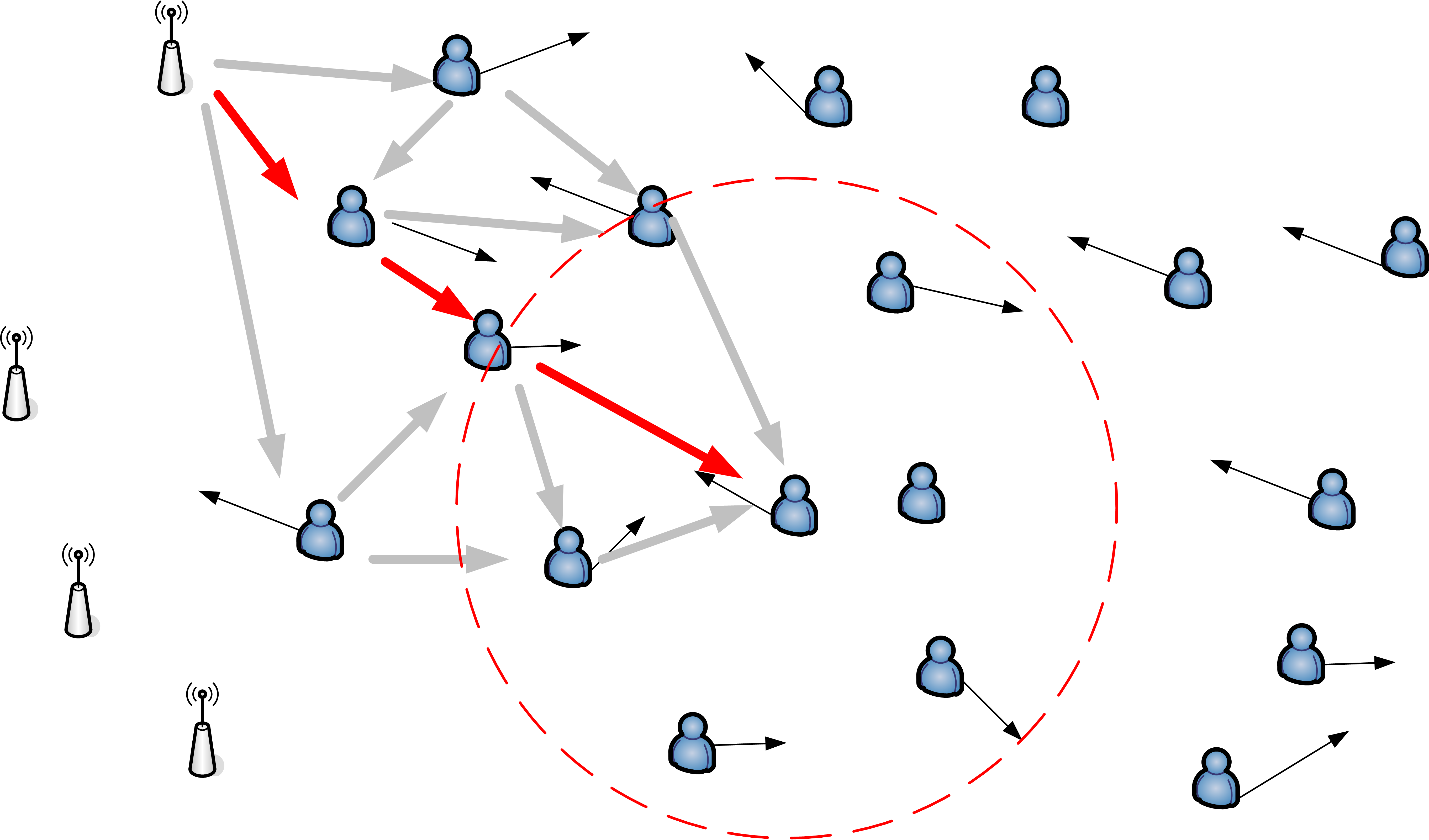
Fig. 1. Choosing the shortest path as anchor distance
• Phase 2 calculate anchor distances - With the aquired data, the node calculates the total distances to all anchors. Probably there will be more than one path to a single anchor which is refined in the next phase.
• Phase 3 greedy phase -The node iterates over all distances for each anchor and choses the shortest one and stores it. In all radio runtime based measuremnt systems the calculated distance will be too long and not too short because of reflections and multipath effects. So this simple greedy algorithm chooses the best possible path to the anchor as shown in Figure 1.
lites, in order be able to locate the unknown position of a node as precise as possible. One simple approach is to use
7
| Interval 5,0 s | Interval 1,0 s | ||
|---|---|---|---|
| Interval 0,5 s | Interval 0,1 s | ||
|
|||
|
|||
| 0 | 60 | 120 | 180 | 240 | 300 |
|---|
50
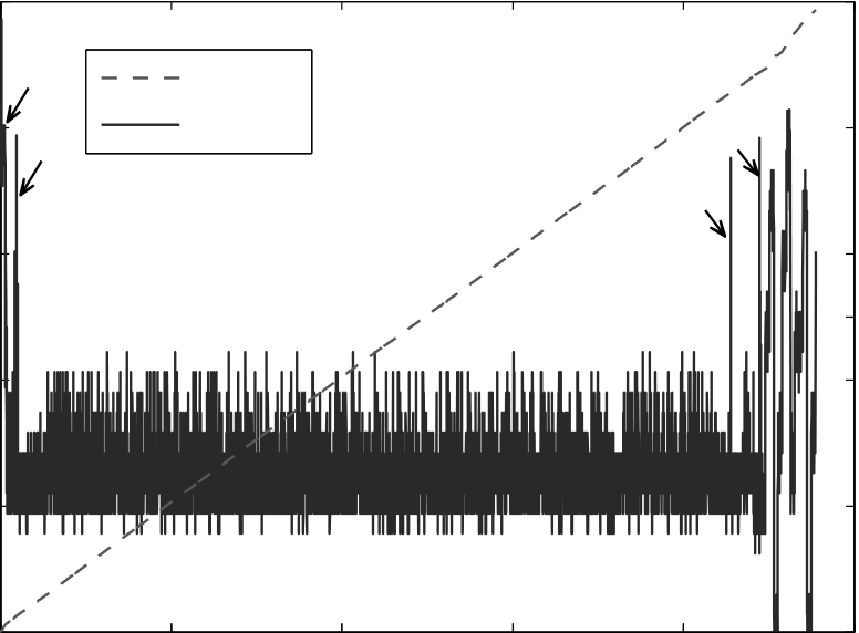
300 Nodes40 100 Nodes Avg.- Error [m]
30 50 Nodes
| 0 | 60 | 120 | 180 | 240 | 300 |
|---|
Time [s] VI. CONCLUSION & FUTURE WORK
Fig. 3. Comparing average localization error by changing the quantity of nodes. Fixed settings: nearest neighbor anchor selection, 4 anchors and 1 second localization interval.
0
| 0 | 60 | 120 | 180 | 240 | 300 |
|---|
Time [s]
8
Remote Incremental Adaptation of Sensor Network Applications
Abstract—Wireless Sensor Networks (WSNs) are deployed for long periods of time, during which a need often arises to dynamically reprogram or retask them. An array of solutions has been proposed to this effect, ranging from full image replacement to virtual machines. However, the capabilities of TinyOS –the current state of the art in sensor node operating systems– are still limited to full image replacement. TinyOS based applications have a modular architecture but during compilation this modularity is lost resulting in a statically linked system image.
In this work we extend TinyOS to allow dynamic exchange of components in WSN applications by conserving their modularity during the compilation process. This generates the possibility of incremental adaptation of sensor nodes’ behavior through partial code replacement. The designed system does not require any alterations in the existing user interfaces, remaining transparent to the user. The evaluation shows that our approach imposes almost no performance overhead for loaded application while keeping a smaller memory footprint than other comparable solutions.
application of the sensor network often requires adaptation
through introduction of new code. Manually collecting all the
desirable feature.
Remote retasking of sensor nodes is mainly challenged by
Considering these constraints, an ideal solution to dynamically
update a nodes functionality would be the one that optimizes
based applications running on sensor nodes. The proposed
system works in two phases; firstly, the existing components
interfaces. This component based structure results in a very modular architecture of TinyOS applications. However, once compiled, this modularity is lost. The NCC compiler when transforming nesC to C mashes up the component structure of the input to make the output conform to the semantics of C. The output is a single monolithic C source file to be compiled by the respective toolchain. We alter this process of compilation by isolating subsets of an application’s con-stituent nesC components and compiling them into ELF files. The resulting files collectively enclose all of the constituent components of the application. These files are transferred to the sensor node which links them together and loads them in the program memory to form the executable binary image again.
The solution we present consists of two main components; Isolater to isolate a single or an integrated group of nesC components and compile them into an ELF object. Second, TinyMan, a runtime ELF linker executing at sensor node and responsible for integrating the ELF objects to form the executable binary image to be loaded in program memory. The working of both of these are detailed as follows.
| Code |
|
Iin (mA) | 10 |
|
C |
|
400 | ||||
|---|---|---|---|---|---|---|---|---|---|---|---|
 |
|||||||||||
| 8 | B | ||||||||||
| 6 | |||||||||||
| a. Before Optimizations | 4 | ||||||||||
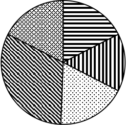
| Fig. 2. | Results of optimizations shown as proportionate change in sizes of | 2 | |||||||||
|
|||||||||||
are available to the loaded application through the global symbol table, which can be used for storing new or updated ELF modules and then integrating them into the existing application.
IV. EVALUATION
We evaluate the proposed system along the lines of major constraints faced in WSNs i.e. energy consumption, process-ing requirements and memory utilization.
| Component | Size (B) | Transfer Energy (mJ) | Savings Factor |
|---|---|---|---|
| BlinkC BlinkAppC LedsC Msp430TimerC |
|
|
|
| Blink w. Deluge | 39024 | 2743.38 | – |
| System | ROM (B) | RAM (B) |
|---|---|---|
| SOS Core TinyOS w. Deluge Bombilla VM |
||
| TinyMan | 15826 | 792 |
|
|
|---|
Keeping the runtime support layer thinner has a positive effect on the runtime computational requirements as well. Dur-ing normal application execution – the most frequent activity for a sensor node – only the interrupt routing component of TinyMan is active, and introduces a short delay in the processing of interrupts. On telos platform the worst case delay is that of 23 instruction cycles – equivalent to processing required for copying eight bytes in memory. No performance depreciation is caused by other components and the code execution remains native.
12
In den vergangenen Jahren f¨uhrte die stetige Weiterentwick-lung von Soft- und Hardware f¨ur Sensornetzwerke zu einem Entwicklungsstand, der nicht mehr nur vermehrt universit¨are, sondern vor allem auch von der Industrie angetriebene Projekte entstehen ließ. L¨angst werden Sensoren zur ¨Uberwachung von Straßen, Ski- und Erdbebengebieten, intelligenten H¨ausern, Transportwegen etc. eingesetzt. Doch w¨ahrend sich Forschung und Entwicklung meist auf die intrinsischen Charakteristiken von Sensornetzwerken konzentrierten, bleibt h¨aufig die Fra-ge, was mit den Sensordaten nach ihrer Erhebung passiert, unbeantwortet. Einerseits fehlen geeignete Gesch¨aftsmodelle und andererseits passende Softwareinfrastrukturen, die eine schnelle Umsetzung der Modelle erlauben.
In dieser Arbeit soll daher eine verteilte Middleware-Infrastruktur vorgestellt werden, welche Anbieter (z.B. un-abh¨angige Sensornetzbetreiber) und Nutzer (z.B. Gesch¨afts-anwendungen) von Sensordaten zusammenbringen soll. An-bieter stellen erhobene Sensordaten in nahezu Echtzeit dem System zur Verf¨ugung und Nachfrager k¨onnen ihr Interesse an bestimmten Daten im System hinterlegen und werden bei Eintreten korrespondierender Ereignisse entsprechend infor-miert. Das System selbst ¨ubernimmt hierbei die Aufgabe zwischen Anbietern und Nachfragenden sowie den von diesen verwendeten Technologien zu vermitteln. Auf diese Weise soll die herrschende Heterogenit¨at verborgen und die vorgestellte Middleware auch f¨ur andere Kontextdaten (z.B. RFID, Nut-zerkontext etc.) verwendet werden k¨onnen.
Ein weiteres Anwendungsszenario findet sich in der Haus-automation. Intelligente H¨auser besitzen eine Vielzahl von Sensoren und Aktuatoren zur Wahrnehmung und Reaktion auf Vorkommnisse im Haus. Ein Server innerhalb des Hauses verarbeitet die Sensordaten und verf¨ugt bereits ’ab Werk’¨uber einige Standard-Reaktionsschemata. Der Besitzer eines intelligenten Hauses m¨ochte die Funktionen dieses Hauses jedoch gerne weitergehend an sein Verhalten individuell anpas-sen. Hierf¨ur soll jedes Familienmitglied eigene Ereignismuster und die zu erfolgende Reaktion des Hauses angeben k¨onnen, allerdings sollen nicht alle Mitglieder der Familie die gleichen Rechte und M¨oglichkeiten bekommen.
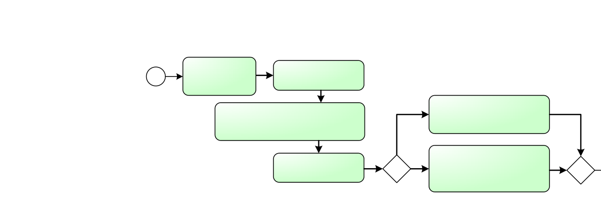
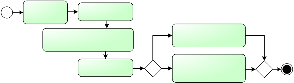
Im n¨achsten Abschnitt III wird nun eine Architektur vorge-stellt, welche die Realisierung der genannten Anwendungssze-narien erm¨oglichen soll. Abschnitt III-A erl¨autert nachfolgend die Funktionen in Bezug auf die Szenarien beispielhaft.
|
||||
|---|---|---|---|---|
| Event Source |
reply | Registration Manager | ||
|
||||
|
||||
Observation
Repository
| Abbildung 1. | Middleware-Architektur | |
|---|---|---|
14
Angenommen das Lagerhaus aus dem Anwendungsbeispiel in Abschnitt II betreibt eine solche Software-Infrastruktur und bietet seinen Klienten entsprechende Dienste an. Das Han-delsunternehmen m¨ochte, wie beschrieben, informiert werden, sobald eines von drei Ereignissen im Lagerhaus eingetreten ist, also sobald der Container eintrifft oder sich versp¨atet und falls Sensorwerte des intelligenten Containers eine Besch¨adigung der TV-Ger¨ate vermuten lassen. Hierf¨ur muss das Handelsun-ternehmen ein Ereignismuster definieren, welches vereinfacht folgendermaßen aussieht:
SELECT * FROM SmartContainerEvent WHERE id BETWEEN x AND y AND
15
RFID-Chips versehenen TV-Ger¨ate von einem externen EPC Information Service abgerufen und gleichzeitig das Sensor-Logbuch des intelligenten Containers an das komplexe Ereig-nis angeh¨angt.
16


