

Coplanar waveguide fed coplanar strip dipole antenna electronics letters
material for advertising or promotional purposes or for creating new collective works for resale or redistribution to servers or lists, or to reuse any copyrighted component of this |
|---|

Microstrip to Parallel Strip Balun as Spiral Antenna Feed
Kalyany Vinayagamoorthy∗, Jacob Coetzee†, Dhammika Jayalath‡
Queensland University of Technology
Brisbane, QLD 4000, Australia
E-mail: k.vinayagamoorthy@qut.edu.au∗, jacob.coetzee@qut.edu.au†, dhammika.jayalath@qut.edu.au‡
A baluns is a transformer used to convert the signals from an unbalanced circuit structure to a balanced configuration. In recent years, a number of wideband antennas fed by wideband baluns such as coplanar waveguide to coplanar stripline balun [1] - [2], and microstrip to coplanar stripline balun [3] - [4], have been reported. However, most balun configurations are limited in bandwidth.
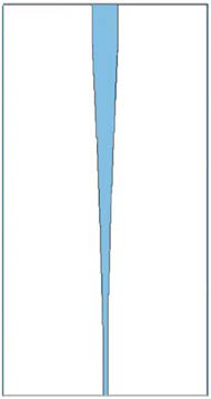
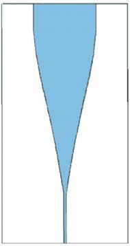
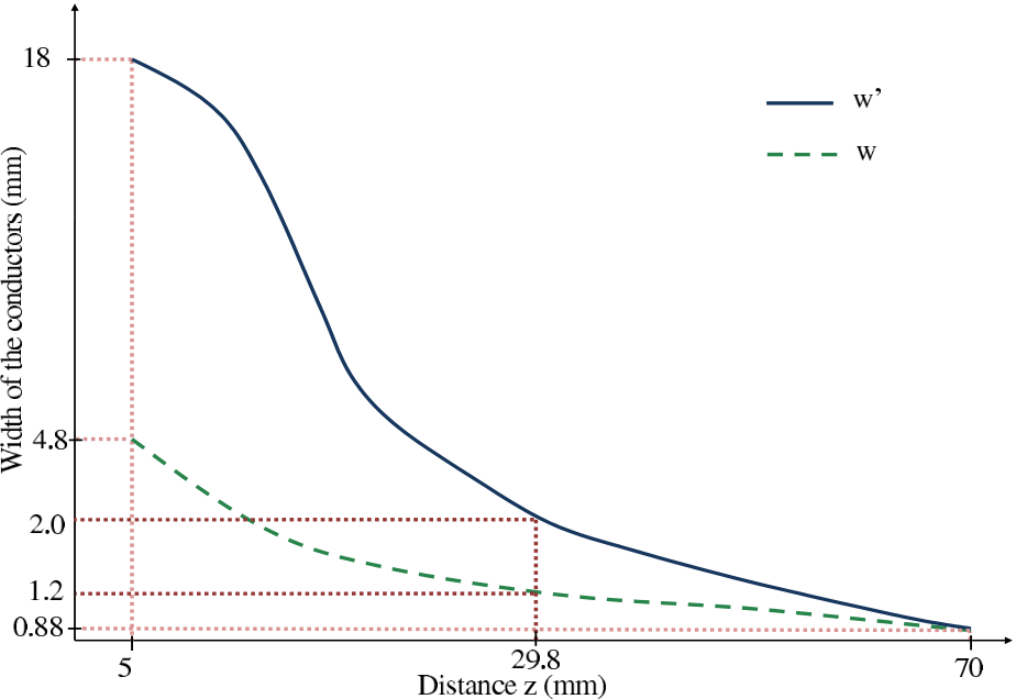
This paper presents a microstrip to parallel strip balun with wideband characteristics. The geometry of the microstrip to parallel strip transition was obtained by implementing a Chebyshev taper in [5]. Another recent example for the microstrip to parallel strip balun was designed using a Hecken taper in order to minimize the return losses and to remove
The input and output impedance of the microstrip line is 50 Ω (Z0) and 188 Ω, where the output impedance of the microstrip line is equal to parallel strip impedance (ZL).
(b)
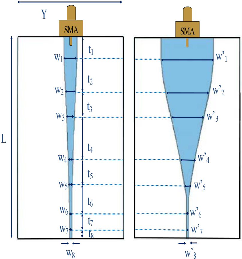
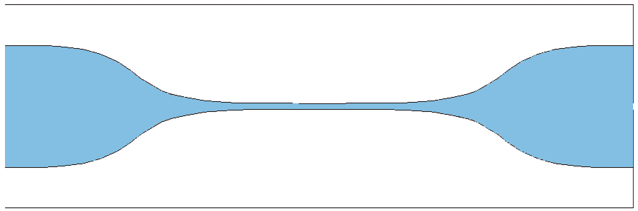
| Configuration of a tapered microstrip to parallel strip with SMA |
|---|
| zi = | i � |
(1) |
|---|
k=1
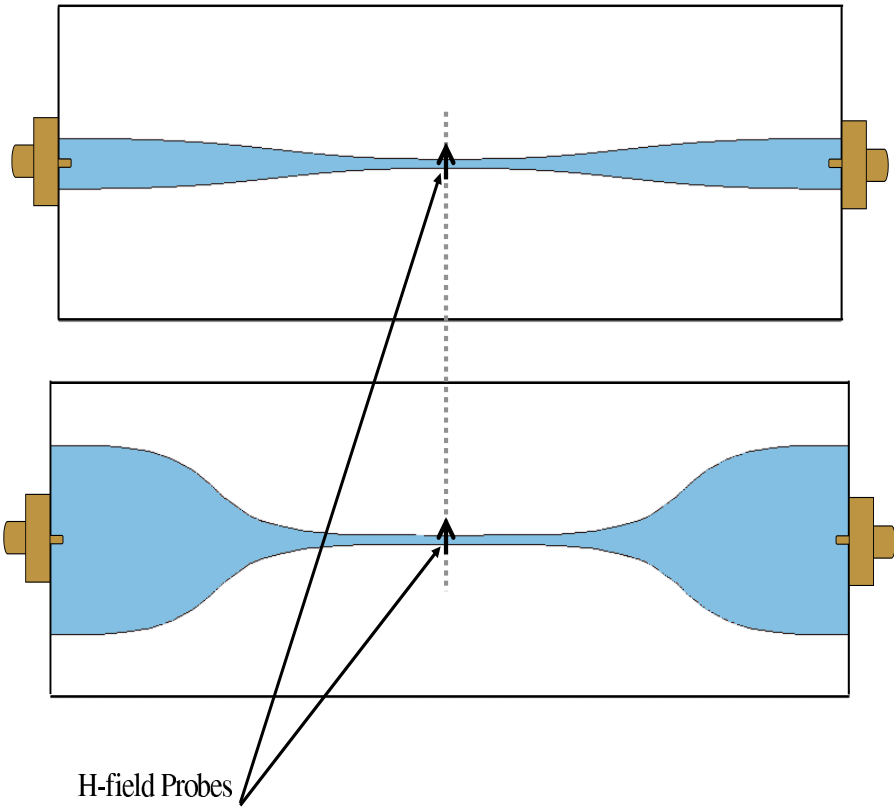
Two single balun structures were joined at the balanced port in a back-to-back configuration to validate the balun performance (Fig. 4).To check the balun’s current balance, two H-field probes were placed at the centrer of the parallel strip outputs (on top and bottom conductors).
| Fig. 4. | Back-to-back connection of the balun with two H-field probes |
|---|
| zi coordinate (mm) | wi (mm) | w′i(mm) | Impedance (Ω) |
|---|---|---|---|
|
|
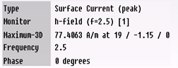
Fig. 6. Surface current distribution at 2.5 GHz of the microstrip to parallel strip balun
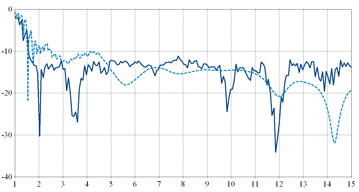
results (Fig. 7), which were obtained using a Rohde Schwarz ZVL vector analyser (frequency range: 300 kHz to 15 GHz). Good agreement between simulation and experimental results were obtained for the both balun structures. However, the mea-sured S11 has some variation with the simulated results due to improper soldering, and the difficulty to align the top and bottom conductors of the balun printed on the same substrate. From the S-parameters results, structure B was selected as an optimum balun to feed the spiral antenna. This microstrip to parallel strip balun exhibits wideband performance from 1.75 to 15 GHz with an insertion loss less than 3 dB and a return loss of better than 10 dB (as shown in Fig. 7) for the back-to-back transition with a significant size reduction. Table II shows the comparison of each balun.
TABLE II
THE COMPARISON OF THE WIDEBAND BALUNS
|
Bandwidth (GHz) | Area (mm2) | |||
|---|---|---|---|---|---|
| 1 - 4 | 90 x 24 | ||||
| 0.45 - 2 | 115 x 8.6 | ||||
| 2 - 14.3 | 70 x 18 | ||||
|
1.75 - 15 | 70 x 18 |
III. CONFIGURATION OF THE SPIRAL ANTENNA WITH BALUN
(a) (b)
(c) (d)
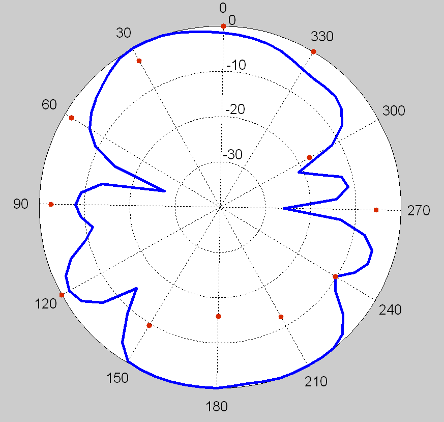
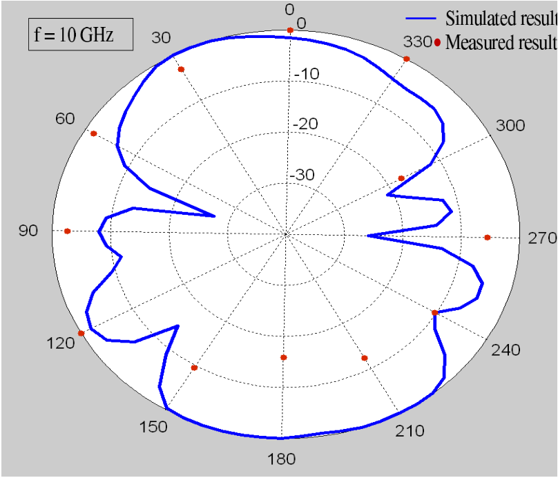
The spiral was set up with a horn antenna (as a receiver, frequency range: 1 to 18 GHz) to measure the radiation patterns at different frequencies. The measured results of the spiral antenna radiation patterns are compared to the simulated results at the frequency of 10 GHz which is shown in Fig. 11.
| Fig. 10. | Measured and simulated S-parameters results for spiral antenna |
|---|
| Fig. 11. 10 GHz | Measured and simulated radiation patterns for the spiral antenna at |
|---|
| Freq/(GHz) | HPBW at E-plane(o) | HPBW at H-plane(o) |
|---|---|---|
| 2 | 94.6 | 81.8 |
| 2.5 | 93.5 | 78.5 |
| 3 | 86.4 | 78.3 |
| 4 | 73.3 | 70.2 |
| 5 | 64.9 | 67.1 |
| 6 | 61 | 60.7 |
| 10 | 53.8 | 47.3 |
| 15 | 42.6 | 34.4 |
In this paper, the design of a microstrip to parallel strip balun using CST Microwave Studio is presented. Two samples were tested and results validated the theory. Computation results reveal a significant size reduction of the balun with a lower insertion loss and a better reflection coefficient. Structure B shows better performance than structure A. The measured bandwidth of the balun is from 1.75 to 15 GHz. The proposed balun was integrated with a spiral antenna to validate its performance as antenna feed. The measured results of the return loss and radiation patterns of the spiral antenna show reasonable performance and agreement with simulated results from the CST Microwave studio simulations. The antenna has a measured bandwidth from 2.5 to 15 GHz for a return loss better than 10 dB. The proposed balun performs well over a wide frequency band and is able to achieve both field and impedance matching.
REFERENCES
[6] P. Carro, J. de Mingo, P. Garcia-Ducar, and C. Sanchez, “Synthesis of hecken-tapered microstrip to paralell-strip baluns for UHF frequency band,” in Microwave Symposium Digest (MTT), 2011 IEEE MTT-S International, June 2011, pp. 1–4.
[7] R. Mongia, I. Bahl, and P. Bhartia, RF and Microwave Coupled-Line Circuits. Artech House, Inc, 1999.


