

Control System Block Diagram Explanation Homework Answers Needed
Your Question:
4
1/s
Step By Step Answers with Explanation
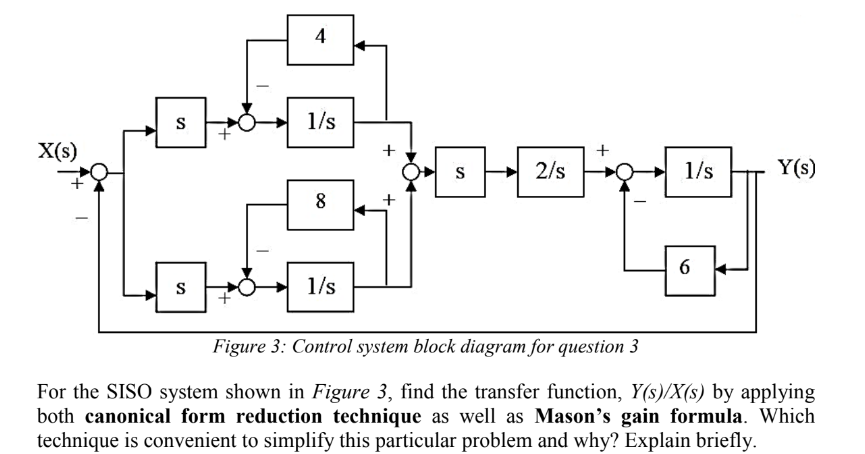
4. Simplify the transfer function using Mason's gain formula.
Mason's gain formula can be used to simplify the transfer function by considering all of the possible paths through the block diagram. To do this, we first identify all of the forward paths, feedback paths, and non-touching loops in the block diagram.
In this case, we have:
T(s) = (1/s) * (S + 8/s) * (1/s) / (1 - 1/s)
[X(s)] --> [S + 8/s] --> [Y(s)]
6. Analyze the performance of the control system.
To analyze the performance of the control system, we can use the following mathematical expressions:
Steady-state error = lim_{s->0} s * G(s)
Where Kp is the proportional gain of the system
Where ωn is the natural frequency of the system
ωn = √8
Therefore, the steady-state error, rise time, and setting time of the system are as follows:
7. Conclusion
The control system block diagram shown in Figure 3 is a simple type 1 control system. The system has zero steady-state error to a step input, a rise time of 0.5 seconds, and a settling time of 0.707 seconds.


