

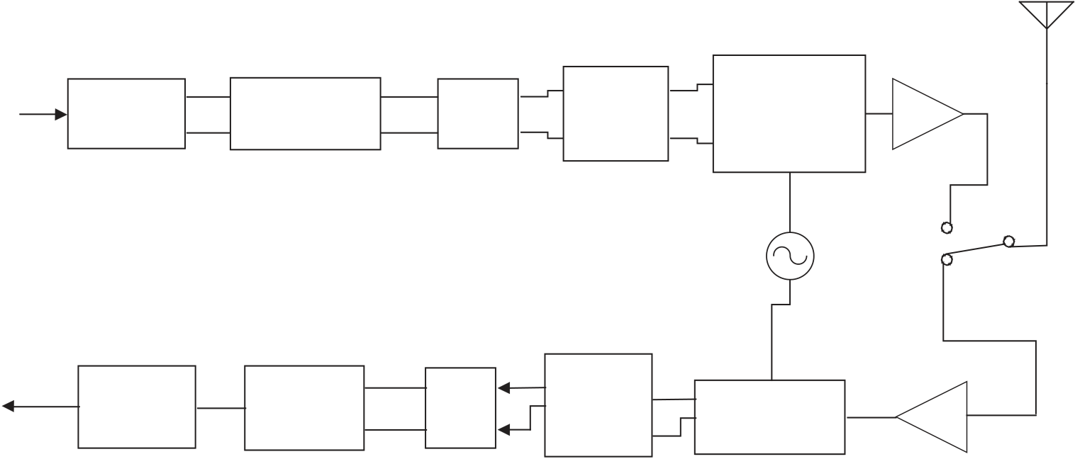
Block diagram the ofdm transmitter and receiver shown figure
|
|
|---|
The available frequency channels in the 5 GHz band in accordance with FCC paragraphs 15.401–15.407 for unlicensed national information infrastructure (U-NII) devices are
| www.newnespress.com |
|---|
| Communications Systems |
|---|
| FEC | Bit to | IFFT | Add | ||
|---|---|---|---|---|---|
| guard | |||||
|
Coding | symbol map |
|
||
| interval |
| FEC | Symbol | FFT | Remove | ||
|---|---|---|---|---|---|
| to bit | guard | ||||
| Decoding | |||||
| interval |
|
||||
| demap |
LNA
| Modulation | Coding Rate | Coded Bits per Subcarrier | Data Bits per OFDM Symbol |
||
|---|---|---|---|---|---|
|
|
1/2 | 1 | 48 | 24 |
| 3/4 | 1 | 48 | 36 | ||
| 1/2 | 2 | 96 | 48 | ||
|
|
3/4 | 2 | 96 | 72 |
| 16-QAM | 1/2 | 4 | 192 | 96 | |
| 16-QAM | 3/4 | 4 | 192 | 144 | |
| 64-QAM | 2/3 | 6 | 288 | 192 | |
| 64-QAM | 3/4 | 6 | 288 | 216 |
shown in Table 19.8 . Channel allocations are 5 MHz apart and 20 MHz spacing is needed to prevent co-channel interference. Twelve simultaneous networks can coexist without mutual interference. Power limits are also shown in Table 19.9 .
Extension of the data rates of 802.11b to those of 802.11a, but on the 2.4 GHz band is covered in supplement 802.11 g. The OFDM physical layer defi ned for the 5 GHz band is applied essentially unchanged to 2.4 GHz. Equipment complying with 802.11 g must also
| www.newnespress.com |
|---|


