

Basic statechart diagram symbols and notations

 |
LAB MANUAL |
LM- CS2357 |
Sub Code & Name: IT6413 SOFTWARE ENGINEERING LAB |
OBJECTIVE:
To develop a mini-project following the 12 exercises listed below.
To Develop Sequence diagrams and Collaboration Diagram
To Add interface to class diagram
To identify memory leaks
To Develop test case hierarchy
Exam Registration.
Stock maintenance system.
e-book management system.
Recruitment system.
Online Quiz System.
Library Management System.
UML
Types of UML Diagrams
Class Diagrams
Package Diagrams
Package diagrams are a subset of class diagrams, but developers sometimes treat them as a separate technique. Package diagrams organize elements of a system into related groups to minimize dependencies between packages.
Object Diagrams
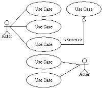
Use Case Diagrams
Sequence Diagrams
Sequence diagrams describe interactions among classes in terms of an exchange of messages over time.
Collaboration Diagrams
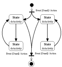
State chart Diagrams
Activity Diagrams
Activity diagrams illustrate the dynamic nature of a system by modeling the flow of control from activity to activity. An activity represents an operation on some class in the system that results in a change in the state of the system. Typically, activity diagrams are used to model workflow or business processes and internal operation.
Component Diagrams
Deployment Diagrams
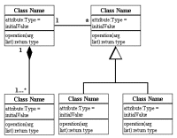
Class diagrams are the backbone of almost every object-oriented method including UML. They describe the static structure of a system.
Basic Class Diagram Symbols and Notations
Active Class
Visibility
Use visibility markers to signifiy who can access the information contained within a class. Private visibility hides information from anything outside the class partition. Public visibility allows all other classes to view the marked information. Protected visibility allows child classes to access information they inherited from a parent class.
Associations
Multiplicity (Cardinality)
Constraint
Place constraints inside curly braces {}.
Composition and Aggregation
Generalization
In real life coding examples, the difference between inheritance and aggregation can be confusing. If you have an aggregation relationship, the aggregate (the whole) can access only the PUBLIC functions of the part class. On the other hand, inheritance allows the inheriting class to access both the PUBLIC and PROTECTED functions of the super class.
Basic Package Diagram Symbols and Notations
Packages
Visibility
Dependency
Dependency defines a relationship in which changes to one package will affect another package. Importing is a type of dependency that grants one package access to the contents of another package.
Basic Use Case Diagram Symbols and Notations
System
Use Case
Draw use cases using ovals. Label with ovals with verbs that represent the system's functions.
Actors
Relationships
Sequence diagrams describe interactions among classes in terms of an exchange of messages over time.
Basic Sequence Diagram Symbols and Notations
Class roles
Class roles describe the way an object will behave in context. Use the UML object symbol to illustrate class roles, but don't list object attributes.
Activation
Messages
Various message types for Sequence and Collaboration
diagrams
Lifielines
Lifielines are vertical dashed lines that indicate the object's presence over time.
Destroying Objects
Loops
A collaboration diagram describes interactions among objects in terms of sequenced messages. Collaboration diagrams represent a combination of information taken from class, sequence, and use case diagrams describing both the static structure and dynamic behavior of a system.
Basic Collaboration Diagram Symbols and Notations
Class roles
Association roles
Messages
Unlike sequence diagrams, collaboration diagrams do not have an explicit way to denote time and instead number messages in order of execution. Sequence numbering can become nested using the Dewey decimal system. For example, nested messages under the first message are labeled 1.1, 1.2, 1.3, and so on. The a condition for a message is usually placed in square brackets immediately following the sequence number. Use a * after the sequence number to indicate a loop.
Basic Statechart Diagram Symbols and Notations
States
Transition
Initial State
A filled circle followed by an arrow represents the object's initial state.
Final State
Synchronization and Splitting of Control
What is a UML Activity Diagram?
An activity diagram illustrates the dynamic nature of a system by modeling the flow of control from activity to activity. An activity represents an operation on some class in the system that results in a change in the state of the system. Typically, activity diagrams are used to model workflow or business processes and internal operation. Because an activity diagram is a special kind of state chart diagram, it uses some of the same modeling conventions.
Basic Activity Diagram Symbols and Notations
Action states
Action Flow
Object Flow
Object flow refers to the creation and modification of objects by activities. An object flow arrow from an action to an object means that the action creates or influences the object. An object flow arrow from an object to an action indicates that the action state uses the object.
Initial State
Final State
Branching
A diamond represents a decision with alternate paths. The outgoing alternates should be labeled with a condition or guard expression. You can also label one of the paths "else."
Synchronization
Swim lanes
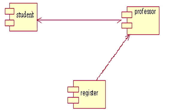
A component diagram describes the organization of the physical components in a system.
Basic Component Diagram Symbols and Notations
Component
A component is a physical building block of the system. It is
represented as a rectangle with tabs.
Interface
Dependencies
Deployment diagrams depict the physical resources in a system including nodes, components, and connections.
Basic Deployment Diagram Symbols and Notations
Component
A node is a physical resource that executes code components.
Association
Components and Nodes
PROBLEM STATEMENTS
2. BOOK BANK
A student of any course should be allowed to borrow books. Book bank books are issued only for their respective courses. A limitation is imposed on the number of books issued to a student.
Number of copies available of the desired book.
The system should be reserve a book for a particular student for 24 hours ifi that book is not currently available. The system should be able to generate the reports regarding the details of the book available in the library at any given time. The corresponding printouts for each entry (issue/return) made in the system should be generated. Security provisions like login authenticity should be provided. Each user should have a user id and password. Record of the users of system should be kept in the log file. Provision should be made for full backup of the system.
Automation: Examination is automated completely. The questions are asked randomly by the system. The checking of questions is done by the system using pre-defined answers fed to the system. Hence results are available immediately after the exam. All exam data is available on the intranet/internet depending upon access rights. Modules need to be cleared sequentially hence flags are set. Passing criteria can be easily set or modified. Time-line can be set for clearing exam and modules.
Study material: Study material is available online and is accessible depending on modules created.
5. E-TICKETING
An e-ticket is the electronic version of the conventional paper ticket. It is an electronic record kept in the airline’s reservations system. You will need to pay through your credit card when booking online. E-tickets can currently be booked online. The system will generate your itinerary receipt and display it on the screen. This will have the key information about your reservation and you will need to print the same and produce it at the airport along with your valid photo identification for check-in. In addition an e-mail will be sent to you which can also be printed. After the booking, you will receive an Itinerary Receipt which holds all details of your booking and trip. A paper ticket is subject to theft and loss, but the Itinerary Receipt is not and it does not matter if it is lost or stolen, since it can easily be replaced. The check-in process is almost the same. Just bring your valid photo identification and your Itinerary Receipt to the check-in counter.
Any official Government issued photo ID card
E-tickets are very popular because they allow extra services like:
It is also possible to have many copies of an e-ticket; hence the "loss" of an airline ticket becomes impossible.
6. SOFTWARE PERSONNEL MANAGEMENT SYSTEM
History of projects done by the employee
Details about the projects assigned to the employee.
Stage 3.) The authorization in Stage 2 occurs after the customer’s information, i.e. name, account number, is sent to the merchant’s processing bank by the debit/credit card companies who are: Visa, Master Card, Discover and American Express. These ‘gateways’ handle the process for using these cards.
Stage 4.) The merchant decides if they want to handle American Express and Discover; all of American Expresses and Discovery’s applications, are handled by them individually which entails banking relationships with merchants etc., The companies issues their own cards, processing set-up and all systems related to the transaction(s) is developed and managed by them.
8. E-BOOK MANAGEMENT SYSTEM
e-book management is primarily an e-book cataloging program. It is designed around the concept of the logical book, where a single database entry corresponds with the same book in a variety of formats. It supports the following formats for cataloging: AZW, AZW1, CBR, CBZ, CHM, EPUB, FB2, HTML, IMP, LIT, LRF, LRX, MOBI, ODT, OEBZIP, OPF, PDB, PDF, PML, PMLZ, PRC, RAR, RB, RTF, SNB, TPZ, TXT and ZIP.
Publisher
Rating
Tags: A flexible system to categorize books.
It also supports metadata retrieval via the Internet for a book based on its ISBN number or its title/author, instead of manually entering the metadata.
10. FOREIGN TRADING SYSTEM
The main users of the systems are the traders, who perform individual trades from their desks, mostly over the phone. Traders are supported by personal workstations, connected to larger corporate servers (or administrators in our parlance). Traders rely on many sources of market information, some informal and some formal; the workstation is used to convey some of this market information, which is provided by the system of interest in two forms: pricing information and market news, from both wire services and financial information providers. Pricing information includes current prices of specifiic commodities (e.g. oil) for dififerent time periods. Market news includes press releases, demand and supply forecasts, wire stories, etc. The system must collect, filter, and disseminate these news to traders.
The Trade Administrator makes a permanent, persistent record of the trade details and notifiies the Position Administrator of the trade.Ifi the trade falls within an existing slate, that slate is simply updated with the details of the new trade.
Ifi no previous trades for the same commodity, movement location and movement period have been made, the Position Administrator creates a new slate. In either case a permanent, persistent record of the slate state is made.
Depending on your choice, the type of submission can be an abstract, full proposal, abstract and proposal together or abstract followed by presentation. The system can process any kind of file formats submitted. The system provides a built-in communication system to send automated or manual emails to all users involved. The email templates can be easily customized.
Author: Submits papers and/or supporting materials to the system via his account.
Conference Manager: Manages the entire system by using the admin panel.
12. BPO MANAGEMENT SYSTEM
The new system will allow students to select four course offerings for the coming semester. In addition, each student will indicate two alternative choices in case the student cannot be assigned to a primary selection. Course offerings will have a maximum of ten students and a minimum of three students. A course offering with fewer than three students will be canceled. For each semester, there is a period of time that students can change their schedule. Students must be able to access the system during this time to add or drop courses. Once the registration process is completed for a student, the registration system sends information to the billing system so the student can be billed for the semester. If a course fills up during the actual registration process, the student must be notified of the change before submitting the schedule for processing.
At the end of the semester, the student will be able to access the system to view an electronic report card. Since student grades are sensitive information, the system must employ extra security measures to prevent unauthorized access.
application. Each transaction must be recorded and the client must have the ability to review all transaction performed against a given account. Recorded transaction must include date, time, transaction type, amount and account balance after the transaction. The application must verify that a client can gain access to his/her account by identification through a PIN code (Personal Identification Number). If the balance is insufficient to cover the requested amount then application should inform the user and terminate the transaction.
15. ONLIE QUIZ SYSTEM
3. The number of questions should be 40 chosen randomly from the database in 3 different areas namely i) Technical ii) logical reasoning and iii) General Knowledge.
4. The questions should be of objective type with multiple options. For each correct answer the participant will receive 1Point and for wrong answer .25Point will be deducted.
2.IEEE SOFTWARE REQUIREMENTS SPECIFIICATION TEMPLATE
2.1 Introduction The introduction of the SRS should provide an overview of the entire SRS. It should contain the following
d) References;
e) Overview.
5.1.2 Scope
This subsection should
5.1.3 Definitions, acronyms, and abbreviations
This subsection should provide the definitions of all terms, acronyms, and abbreviations required to properly interpret the SRS. This information may be provided by reference to one or more appendixes in the SRS or by reference to other documents.
c) Specify the sources from which the references can be obtained.
This information may be provided by reference to an appendix or to another document.
5.2 Overall description
This section of the SRS should describe the general factors that affect the product and its requirements. This section does not state specific requirements. Instead, it provides a background for those requirements, which are defined in detail in Section 3 of the SRS, and makes them easier to understand. This section usually consists of six subsections, as follows:
e) Assumptions and dependencies;
f) Apportioning of requirements.
these constraints could include
a) System interfaces;
f) Memory;
g) Operations;
This should specify the following:
a) The logical characteristics of each interface between the software product and its users.
This should specify the logical characteristics of each interface between the software product and the hardware components of the system. This includes configuration characteristics (number of ports, instruction sets, etc.). It also covers such matters as what devices are to be supported, how they are to be supported, and protocols. For example, terminal support may specify full-screen support as opposed to line-by-line support.
5.2.1.4 Software interfaces
Version number;
Source.
This should specify the various interfaces to communications such as local network protocols, etc.
5.2.1.6 Memory constraints
b) Periods of interactive operations and periods of unattended operations;
c) Data processing support functions;
b) Specify the site or mission-related features that should be modified to adapt the software to a particular installation.
5.2.2 Product functions
5.2.3 User characteristics
This subsection of the SRS should describe those general characteristics of the intended users of the product including educational level, experience, and technical expertise. It should not be used to state specific requirements, but rather should provide the reasons why certain specific requirements are later specified
c) Interfaces to other applications;
d) Parallel operation;
i) Reliability requirements;
j) Criticality of the application;
5.2.6 Apportioning of requirements
This subsection of the SRS should identify requirements that may be delayed until future versions of the system.
c) All requirements should be uniquely identifiable.
d) Careful attention should be given to organizing the requirements to maximize readability.
b) Description of purpose;
c) Source of input or destination of output;
h) Screen formats/organization;
i) Window formats/organization;
Functional requirements should define the fundamental actions that must take place in the software in accepting and processing the inputs and in processing and generating the outputs. These are generally listed as shall statements starting with The system shall
These include
2) Communication facilities
3) Error handling and recovery
It may be appropriate to partition the functional requirements into sub functions or sub processes. This does not imply that the software design will also be partitioned that way.
5.3.3 Performance requirements
Static numerical requirements are sometimes identified under a separate section entitled Capacity.Dynamic numerical requirements may include, for example, the numbers of transactions and tasks and the amount of data to be processed within certain time periods for both normal and peak workload conditions.All of these requirements should be stated in measurable terms. For example,
95% of the transactions shall be processed in less than 1 s.
a) Types of information used by various functions;
b) Frequency of use;
5.3.5 Design constraints
This should specify design constraints that can be imposed by other standards, hardware limitations, etc.
b) Data naming;
c) Accounting procedures;
5.3.6.1 Reliability
This should specify the factors required to establish the required reliability of the software system at time of delivery.
a) Utilize certain cryptography techniques;
b) Keep specific log or history data sets;
This should specify attributes of software that relate to the ease of maintenance of the software itself. There may be some requirement for certain modularity, interfaces, complexity, etc. Requirements should not be placed here just because they are thought to be good design practices.
5.3.6.5 Portability
d) Use of a particular compiler or language subset;
e) Use of a particular operating system.
5.3.7.2 User class
Some systems provide different sets of functions to different classes of users. For example, an elevator control system presents different capabilities to passengers, maintenance workers, and Fire Fighters. When organizing this section by user class, the outline in A.3 should be used.
5.3.7.5 Stimulus
Some systems can be best organized by describing their functions in terms of stimuli. For example, the functions of an automatic aircraft landing system may be organized into sections for loss of power, wind shear, sudden change in roll, vertical velocity excessive, etc. When organizing this section by stimulus, the outline in A.6 should be used.
used.
5.3.8 Additional comments
a) Table of contents;
b) Index;
The appendixes are not always considered part of the actual SRS and are not always necessary. They may include
a) Sample input/output formats, descriptions of cost analysis studies, or results of user surveys;
Version <1.0>
Revision History
Basic Package Diagram Symbols and Notations 9
Basic Use Case Diagram Symbols and Notations 11
Basic Activity Diagram Symbols and Notations 17
Basic Component Diagram Symbols and Notations 19
3 Preconditions 46
4 Basic Flow of Events 46
Project Risk Management Plan Purpose 55
Stakeholder Roles and Responsibilities 55
Use Case Name
Brief Description
[This use case starts when the actor does something. An actor always initiates use Cases. The use case should describe what the actor does and what the system does in response. It should be phrased in the form of a dialog between the actor and the system.
The use case should describe what happens inside the system, but not how or why. Ifi information is exchanged, be specific about what is passed back and forth. For example, it is not very illuminating to say that the Actor enters customer information. It is better to say the Actor enters the customer’s name and address. A Glossary of Terms is often useful to keep the complexity of the use case manageableyou may want to define things like customer information there to keep the use case from drowning in details.
< First Alternative Flow >
[More complex alternatives should be described in a separate section, which is referred to in the Basic Flow subsection of Flow of Events section. Think of the Alternative Flow subsections like alternative behavior each alternative flow represents alternative behavior, many times because of exceptions that occur in the main flow. They may be as long as necessary to describe the events associated with the alternative behavior. When an alternative flow ends, the events of the main flow of events are resumed unless otherwise stated.]
Special Requirements
[A special requirement is typically a non-functional requirement that is specifiic to a use case, but is not easily or naturally specifiied in the text of the use case’s event flow. Examples of special requirements include legal and regulatory requirements, application standards, and quality attributes of the system to be built including usability, reliability, performance or supportability requirements. Additionally, other requirementssuch as operating systems and environments, compatibility requirements, and design constraintsshould be captured in this section.]
Post-Conditions
[A post-condition of a use case is a list of possible states the system can be in immediately after a use case has finished.]
[Definition of the location of the extension point in the flow of events.]
WITHDRAW MONEY: USE CASE SPECIFIICATION
1 Brief Description
This use case describes how the Bank Customer uses the ATM to withdraw money to his/her bank account.
2 Actors
2.1 Bank Customer
2.2 Bank
3 Preconditions
4 Basic Flow of Events
4. The ATM prompts for an account. See Supporting Requirement SR-yyy for account types that shall be supported.
5. The Bank Customer selects an account.
10. The Bank Card is returned.
11. The receipt is printed.
5 Alternative Flows
5.1 Invalid User
5.2 Wrong account
1. The ATM shall display the message "Invalid Account – please try again".
2. The use case resumes at step 4.
5.3 Wrong amount
5.4 Amount Exceeds Withdrawal Limit
1. the ATM shall display a warning message, and ask the Bank Customer to reenter the amount
2. The use case resumes at step 7
5.5 Amount Exceeds Daily Withdrawal Limit
5.6 Insufficient Cash
1. The ATM will display a warning message, and ask the Bank Customer to reenter the amount.
2. The use case resumes at step 7.
5.7 No Response from Bank
4. The ATM shall indicate that it is "Closed".
5. The use case ends with a failure condition.
5.8 Money Not Removed
5.9 Quit
If at point prior to step 8 in the basic flow the Bank Customer selects Quit, then
1. The ATM shall print a receipt indicating the transaction was cancelled.
6 Key Scenarios
6.1 No Response from Bank
7 Post-conditions
7.1 Successful Completion
7.2 Failure Condition
8 Special Requirements
[SpReq:WC-1] The ATM shall dispense cash in multiples of $20.
[SpReq2:WC-2] The maximum individual withdrawal is $500.
COMPONENT DIAGRAM
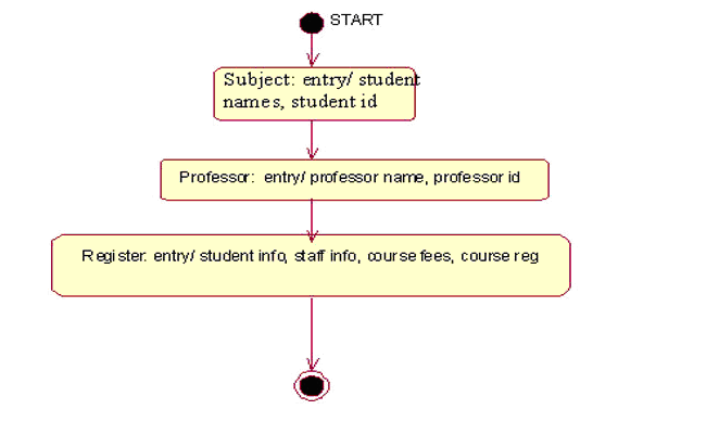
STATE CHART DIAGRAM
CLASS DIAGRAM

Department:
Product or Process:
| Version | Date | Author | Change Description |
Project Risk Management Plan Purpose
Stakeholder Roles and Responsibilities
Risk Management Process and Activities
| Risk Management Activity | Risk Management Task Description | Ownership (Participants) |
| [Risk Identification] | [Identify the techniques that are used to identify risk factors at the beginning of the project and on an ongoing basis. This may involve a formal risk assessment workshop, a brainstorming session, and interviews at the beginning of each major milestone phase.] | [Identify project team members and key stakeholders to be involved.] |
Risk Management Plan Audit Log
Risk Assessment and Management Table
| Risk Type | Risk and Description | Risk Chance | Risk Impact | Risk Priority | Risk Owner |
| [Project Management Risks] | [Inadequate project definition Stakeholders uncertain of project scope] |
[Medium] | [Medium] | [Medium] | |


