

Assume the standard rig floor arrangement shown the lecture lbf
Drilling System Design
Khalil Rahman
Principal Geomechanics Specialist Baker RDS, Perth, Australia
Email: Tel: 93542793
 |
|---|
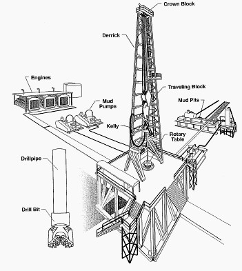
HOISTING SYSTEM:Derrick
respectively.
BLOCK & TACKLE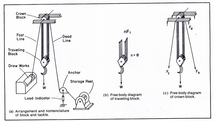
The frictionless system efficiency, E = Ph/Pi = 1,
Because nFf = W for the frictionless system.
|
|---|
Line Rope Specification
• A derrick usually has four legs,
• Loads applied on all legs may not be equal,
• All legs must be strong enough to carry its load,• Legs are designed based on the maximum load,• How to calculate the maximum load carried by a leg,• What is derrick efficiency factor usually used in the industry?
Derrick Design
Depends on the arrangement of the
| A | B |
|
|
|---|---|---|---|
| |
|
||
| | |||
| |
Derrick Design
| F | n | | 4 |
|
|
|---|---|---|---|---|---|
| de |
|
n |
|
|---|
W = 300,000 lbf; n = 8, E = 0.841 (from Table 1.2),
(1) Ff = W/En = 300,000/(0.841 x 8) = 44,590 lbf
| F | 1 | | E | | En |
|
||||||||
|---|---|---|---|---|---|---|---|---|---|---|---|---|---|---|
| d | En | | ||||||||||||
| 1 | | .0 841 | | .0 841 8 | ||||||||||
|
| |||||||||||||
|
||||||||||||||
| E | F d | 382,090 | ||||
|---|---|---|---|---|---|---|
|
F de | 450 ,000 |
DESIGN OF HOISTING SYSTEM
DESIGN OF HOISTING SYSTEM
| • | We know |
|
||
|---|---|---|---|---|
Strength/Ff = 2; i.e. strength = 2x74316 = 148,633 lbf
DESIGN OF HOISTING SYSTEM
DESIGN OF HOISTING SYSTEM
|
|---|


