

And turbine inlet pressure and temperature mpa and
Solved step by step with explanation: Determine the state points of the refrigerant in the cycle.
To solve this problem, we'll use the following steps:
Determine the state points of the refrigerant in the cycle.
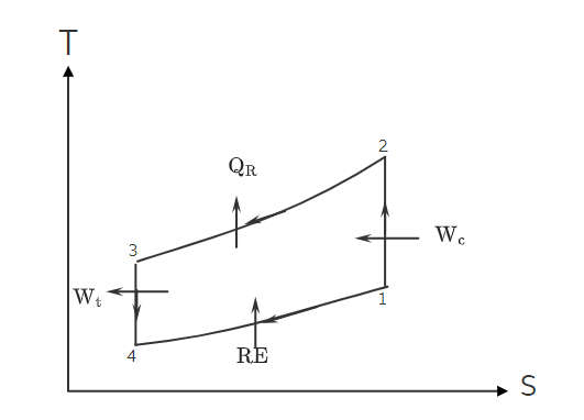
Draw the schematic representation and T-s diagram of the refrigeration cycle.
Outlet from the compressor (4): P4 = P2 T4 = T2
Heat transfer from the cooling medium (Qin): Qin = cp * (T1 - T4)
Specific heat values for air: Since the problem assumes constant specific heats, we can use average specific heat values for air within the given temperature range. The specific heat at constant pressure (cp) for air can be approximated as 1.005 kJ/(kg·K).
Calculate the values using the given data and formulas:
Substitute the given values into the formulas:
Heat transfer from the cooling medium per unit mass flow rate (Qin): Qin = 1.005 * (15 - (-50))
Heat transfer from the cooling medium per unit mass flow rate (Qin): Qin = 1.005 * (15 + 50) kJ/kg
Power required for the compressor (Wcomp): Wcomp = 1.005 * (-50 - 15) kJ/kg
Heat transfer from the cooling medium per unit mass flow rate (Qin): Qin = cp * (T1 - T4)
To find T4, we know that T4 = T3 = T1 = 15 °C.
The power required for the compressor (Wcomp) is -67.025 kJ/kg.
Power generated by the turbine (Wturb): Wturb = cp * (T2 - T3)


