
And equation with becomesthe power waveform depicted figure


| 762 |
|
s t e a d y | π/ω | 2π/ω | ||||
|---|---|---|---|---|---|---|---|---|
| vi |
|
|||||||
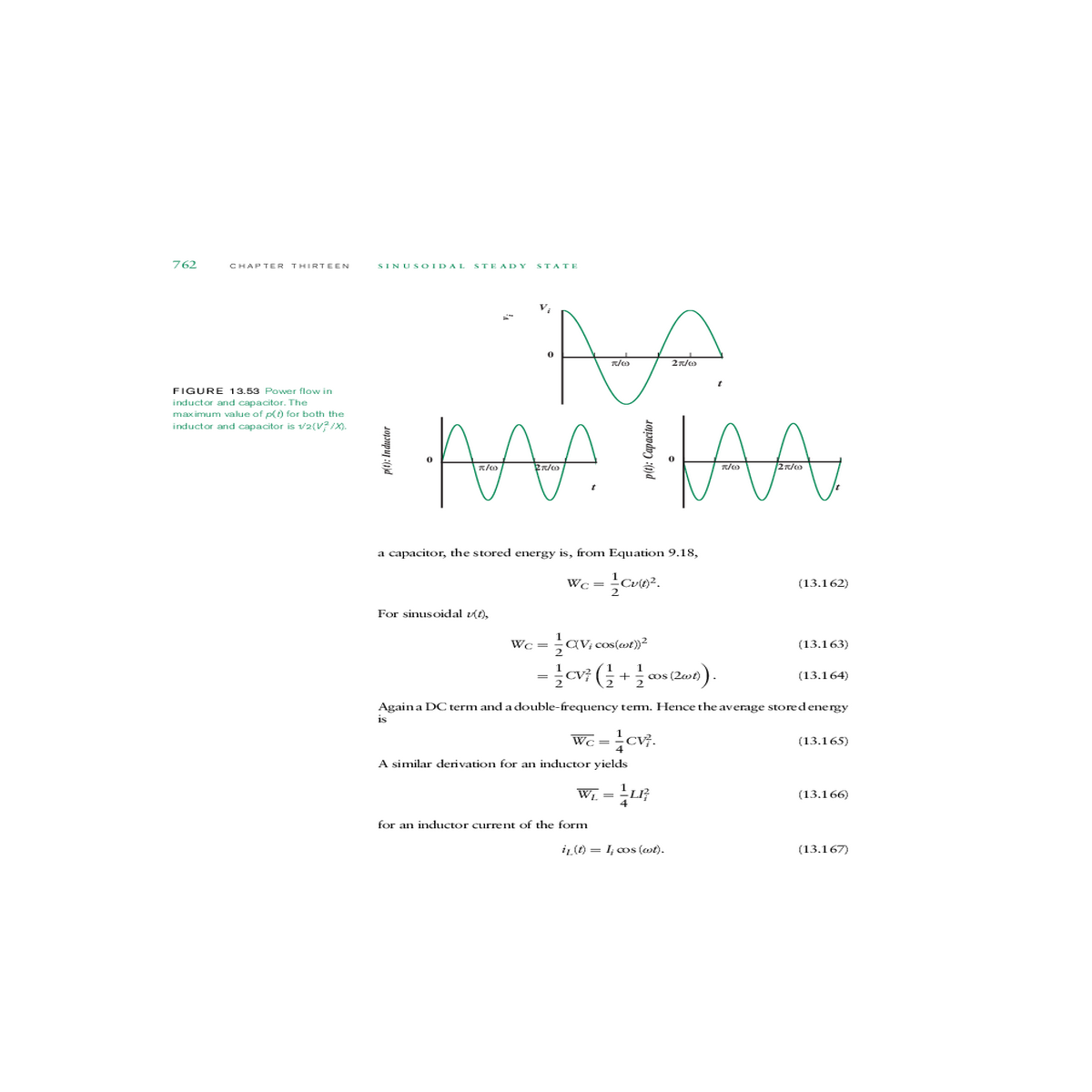
| FIGURE 13.53 Power flow in | ||||||||
| 0 | ||||||||
inductor and capacitor. The
| maximum value of p(t) for both the | p(t): Inductor | 0 | π/ω | 2π/ω | t | p(t): Capacitor | π/ω | 2π/ω | t | |
|---|---|---|---|---|---|---|---|---|---|---|
| inductor and capacitor is 1/2(V2 i/X). |
| WC =1 | (13.162) |
|---|
| WC =1 | C(Vi cos(ωt))2 | cos (2ωt)� |
|
(13.163) | ||
|---|---|---|---|---|---|---|
| (13.164) | ||||||
| CV2 i | �1 | +1 | ||||
| =1 | ||||||
Again a DC term and a double-frequency term. Hence the average stored energy is
| WC =1 | (13.165) |
|---|
| WL =1 | (13.166) |
|---|
iL(t) = Ii cos (ωt). (13.167)


| vi | 13.7 Power and Energy in an Impedance | 763 | |||||||
|---|---|---|---|---|---|---|---|---|---|
| p | |||||||||
|
|||||||||
|
|||||||||
|
|||||||||
| 0 | π/ω | 2π/ω | t | ||||||
| π/ω | |||||||||
| t | |||||||||
For the general case when the network contains resistors, capacitors, and induc-tors, the power flow will have some intermediate form between Figure 13.52 and Figure 13.53. Assuming that the circuit is net inductive at the frequency of
|
|
|---|---|
| 13.7.4 | |
| i(t) |
|
||||||
|---|---|---|---|---|---|---|---|
1 |
|||||||
| + | R | ||||||
| - | |||||||
| I | 1/jωC | R | |||||
| Vi | |||||||
| p1 |
|
(13.171) | FIGURE 13.55 Series RC | ||||
| = |
|
||||||
| =1 | (13.172) | ||||||


