CS147 Computer Architecture Project 1
MIPS Project Question
Simulation of Multiplication and Division Hardware
A. Purpose
MIPS has instructions for (integer) multiplication and division. In the project, we will study the hardware designs how to implement multiplication and division with the basic shift, addition and subtraction operations. We will write MIPS programs to simulate the operations of the hardware designs at each step. Two versions of the multiplication and division hardware will be studied. Read chapter 3 of the textbook for more details and illustrations with examples.
B. Testing
Your programs will be tested using the provided program test.asm. To make sure your programs ex.3.xx can be called and run by test.asm, you need
- put all the program files ex.3.xx.asm and test.asm in same "directory".
- add the following in the beginning of your ex.3.xx.asm program files..globl ex.3.xx
.text ex.3.xx:
- Another provided program display.asm is provided so that you could use ”jal display” to display the tile of each test case like the following:
****************
A=50 B=10 N=6
****************
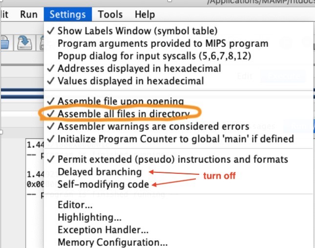
- To assemble all the programs of the project on MARS, you need to turn on the option “To assemble all the files in the same directory”. Also, the “Delayed Branching” option is off.
D. Program to simulate the first version of multiplication hardware
(Source: Exercise 3.12 in the textbook)
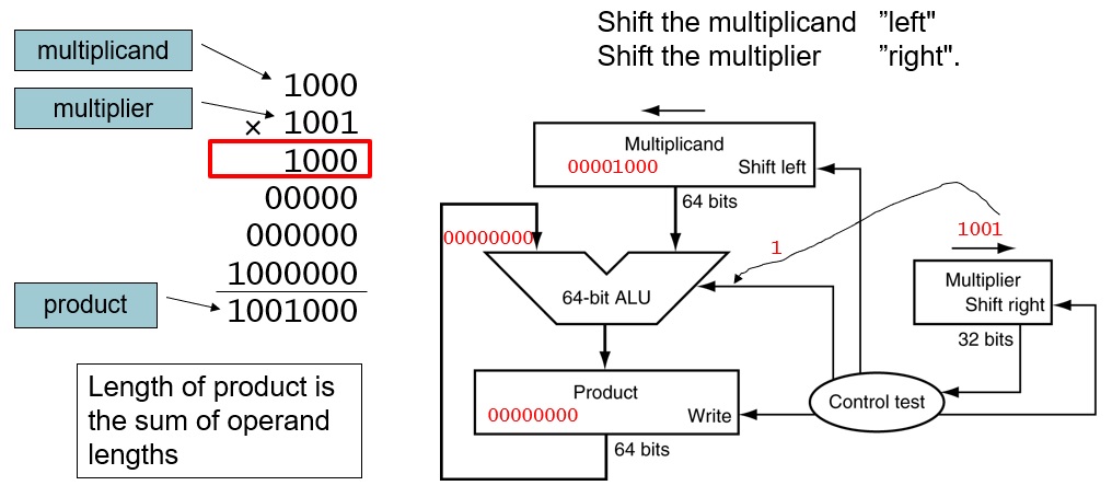
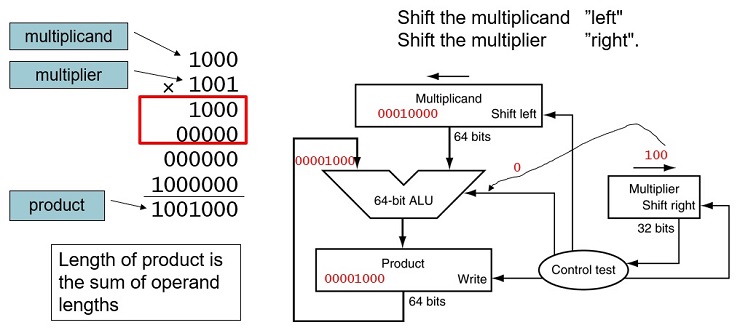
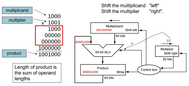
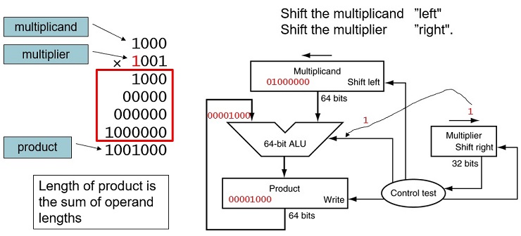
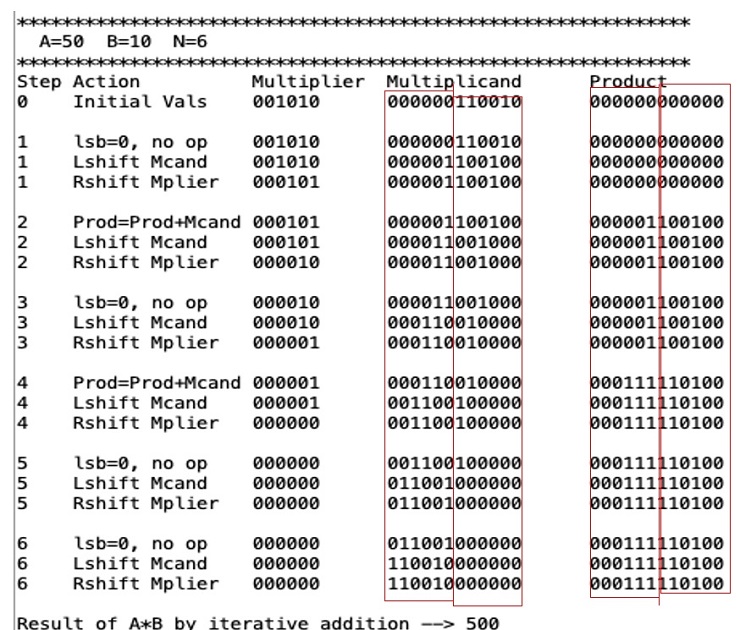
Write a MIP program, ex.3.12.asm, to simulate the multiplication performed by the hardware described in Figure 3.3, for two unsigned n-bit integers A and B, where 1 n 16. The inputs A, B, and n will be assumed to be in $a0, $a1, and $a2 when the program is called.Your program should show the contents of each registers and their operations at each step similar to the example shown below, where A and B are both 6-bit unsigned integers 1100102 and 0010102 (5010 and 1010), respectively. The inputs to the program are two unsigned n-bit integers A and B in $a0 and $a1, and the number of bits (n) in $a2. Note that your program must display numbers with exactly n bits for each number.
A starter program for 32-bit numbers is provided along with this assignment in Canvas. Also, note that we can use a single register to store the product since 1 n 16.
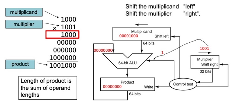
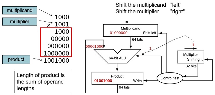
FIGURE 3.3 First version of the multiplication hardware.The Multiplicand register, ALU, and Product register are all 64 bits wide, with only the Multiplier register containing 32 bits. (Appendix B describes ALUs.) The 32-bit multiplicand starts in the right half of the Multiplicand register and is shifted left 1 bit on each step. The multiplier is shifted in the opposite direction at each step. The algorithm starts with the product initialized to 0. Control decides when to shift the Multiplicand and Multiplier registers and when to write new values into the Product register.
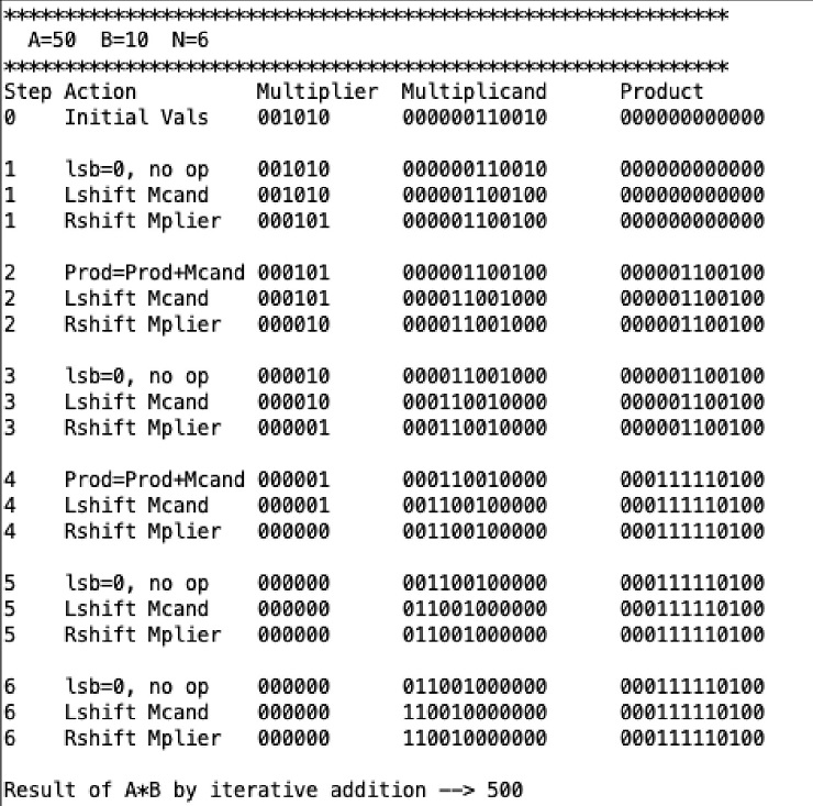
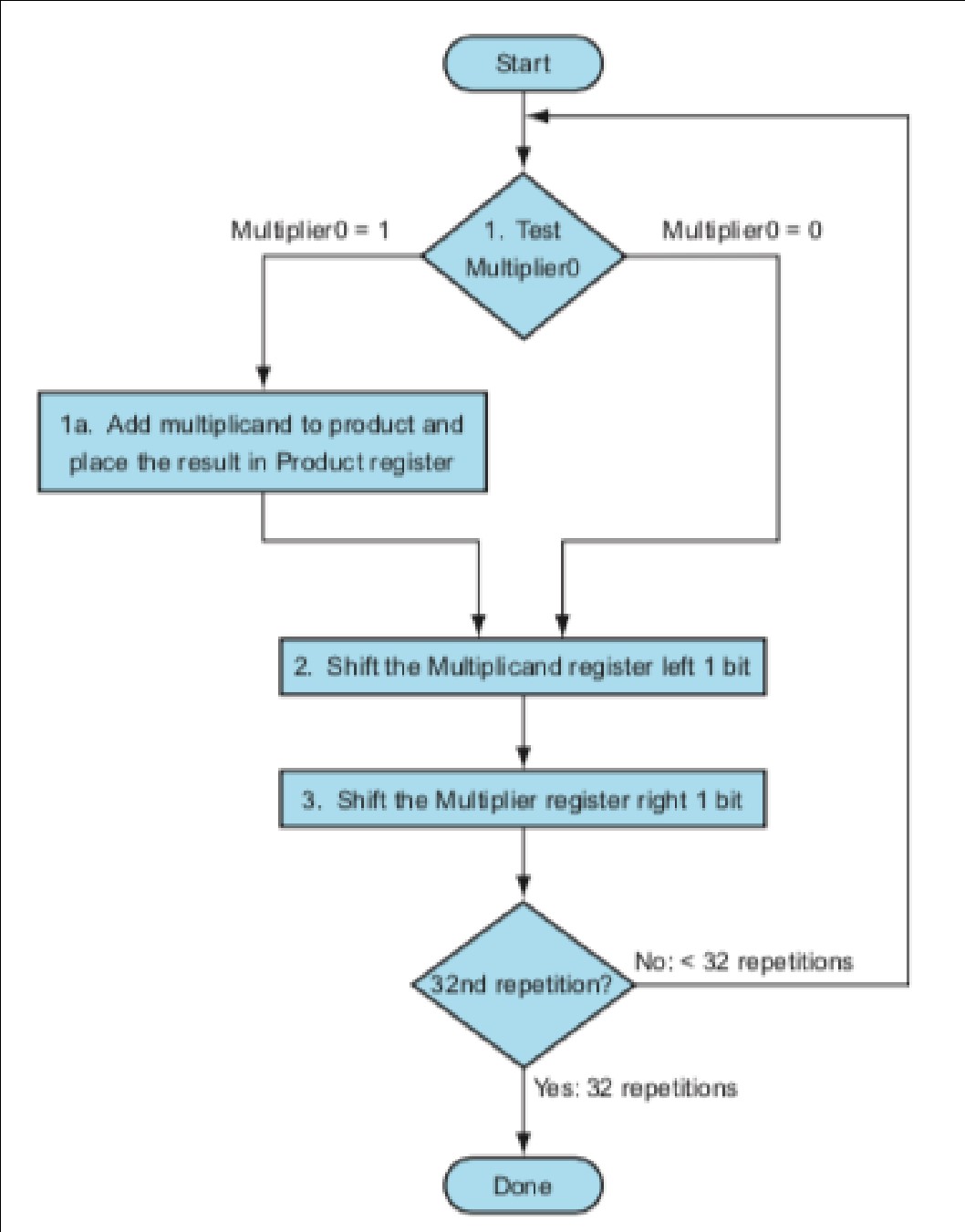
FIGURE 3.4 The first multiplication algorithm, using the hardware shown in Figure 3.3. if the least significant bit of the multiplier is 1, add the multiplicand to the product. If not, go to the next step. Shift the multiplicand left and the multiplier right in the next two steps. These three steps are repeated 32 times.
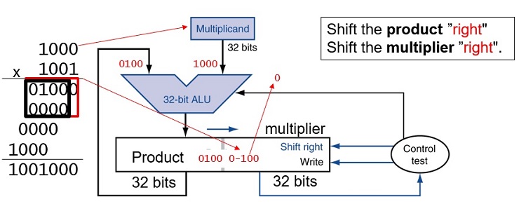
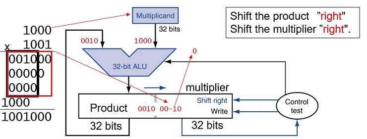
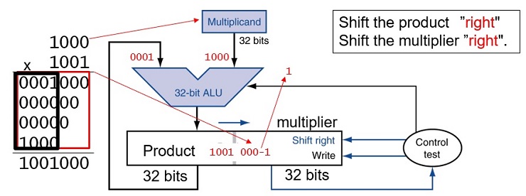
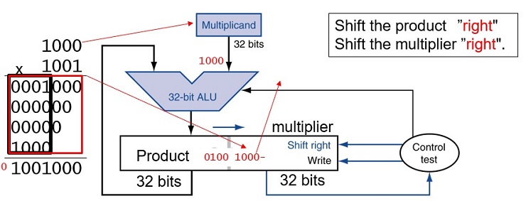
E. Program to simulate the refined multiplication hardware
(Source: Exercise 3.13 in the textbook)
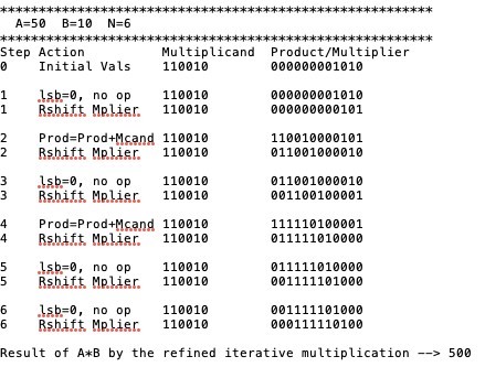
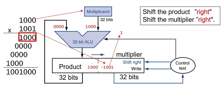
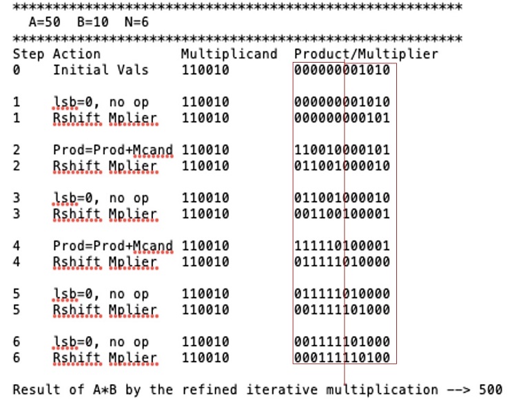
Write a program, named ex.3.13.asm, that will simulate the refined version of the multiplication hardware described in Figure 3.5 and display the numbers as shown in the table below.
A starter program for 32-bit numbers is provided along with this assignment in Canvas.
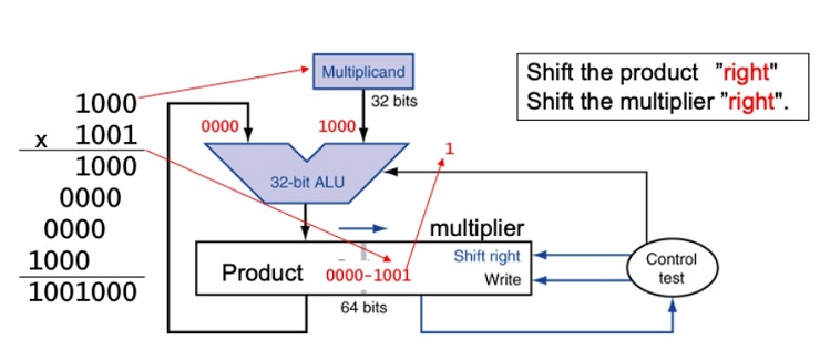
Figure 3.5: Refined version of the multiplication hardware. Compare with the first version in Figure 3.3. The Multiplicand register, ALU, and Multiplier register are all 32 bits wide, with only the Product register left at 64 bits. Now the product is shifted right. The separate Multiplier register also disappeared. The multiplier is placed instead in the right half of the Product register. These changes are highlighted in color. (The Product register should really be 65 bits to hold the carry out of the adder, but it’sshown here as 64 bits to highlight the evolution from Figure 3.3.)
F. Program to simulate the first version of the division hardware
(Source: Exercise 3.18 in the textbook)
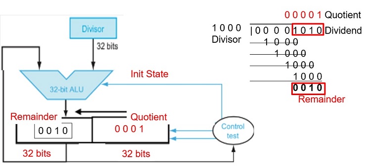
Repeat the process similar to the previous work, but this time write the program, named ex.3.18.asm, to simulate the division hardware as described in Figure 3.8. Your program should show the contents of each registers and their operations at each step similar to the example shown below, where the dividend is 1111002 (6010) and divisor is 0100012 (1710). Again, your program must display numbers with exactly n bits. You could lose 5pt if your program cannot work for different value of n.
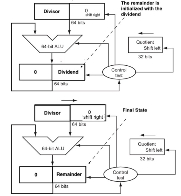
FIGURE 3.8 First version of the division hardware. The Divisor register, ALU, and Remainder register are all 64 bits wide, with only the Quotient register being 32 bits. The 32-bit divisor starts in the left half of the Divisor register and is shifted right 1 bit each iteration. The remainder is initialized with the dividend. Control decides when to shift the Divisor and Quotient registers and when to write the new value into the Remainder register.
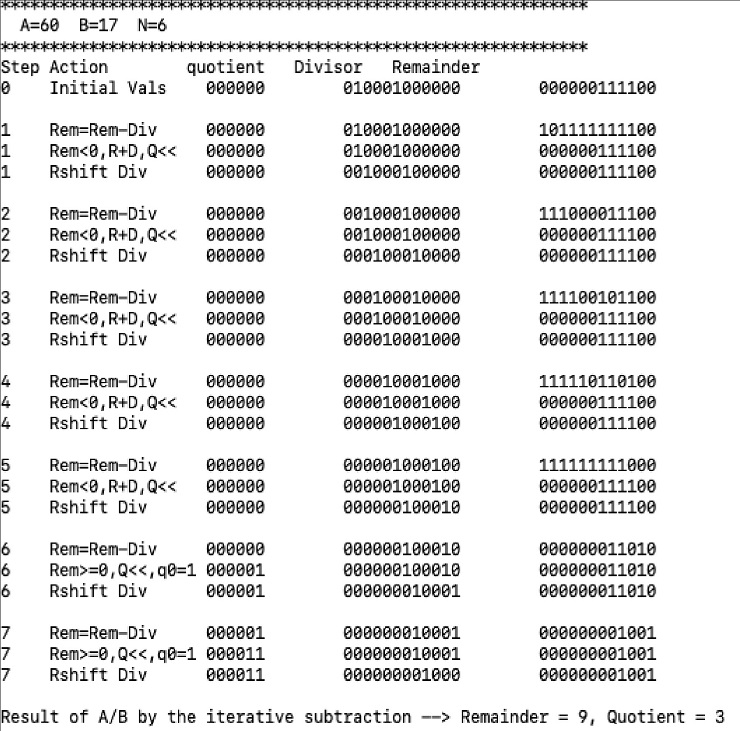
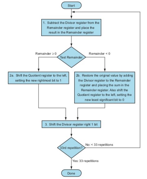
Figure 3.9. A division algorithm, using the hardware in Figure 3.8. If the remainder is positive, the divisor did go into the dividend, so step 2a generates a 1 in the quotient. A negative remainder after step 1 means that the divisor did not go into the dividend, so step 2b generates a 0 in the quotient and adds the divisor to the remainder, thereby reversing the subtraction ofstep 1. The final shift, in step 3, aligns the divisor properly, relative to the dividend for the next iteration. These steps are repeated 33 times.
G. Program to simulate the improved version of the division hardware
(Source: Exercise 3.19 in the textbook)
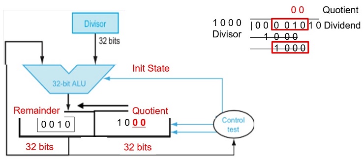
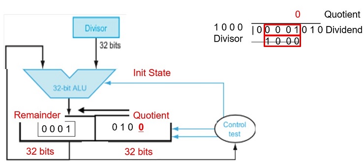
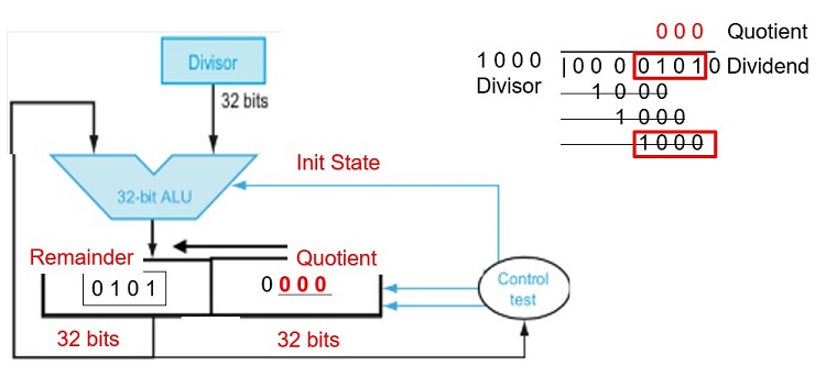
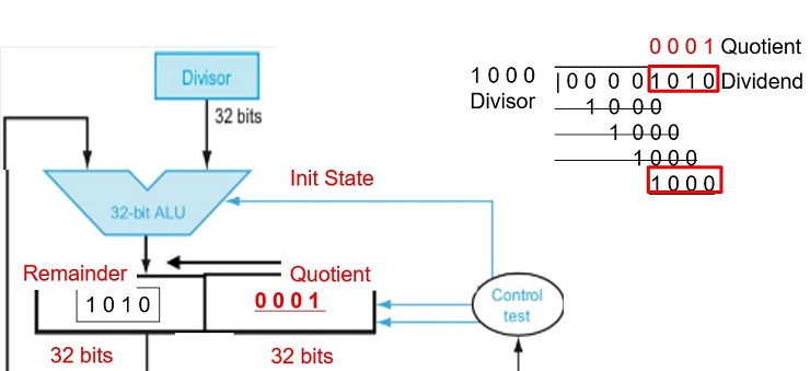
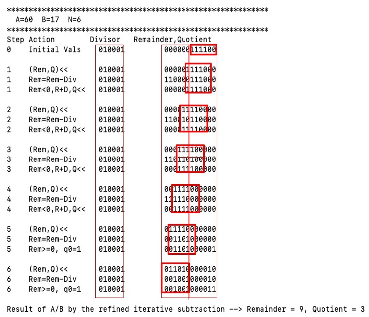
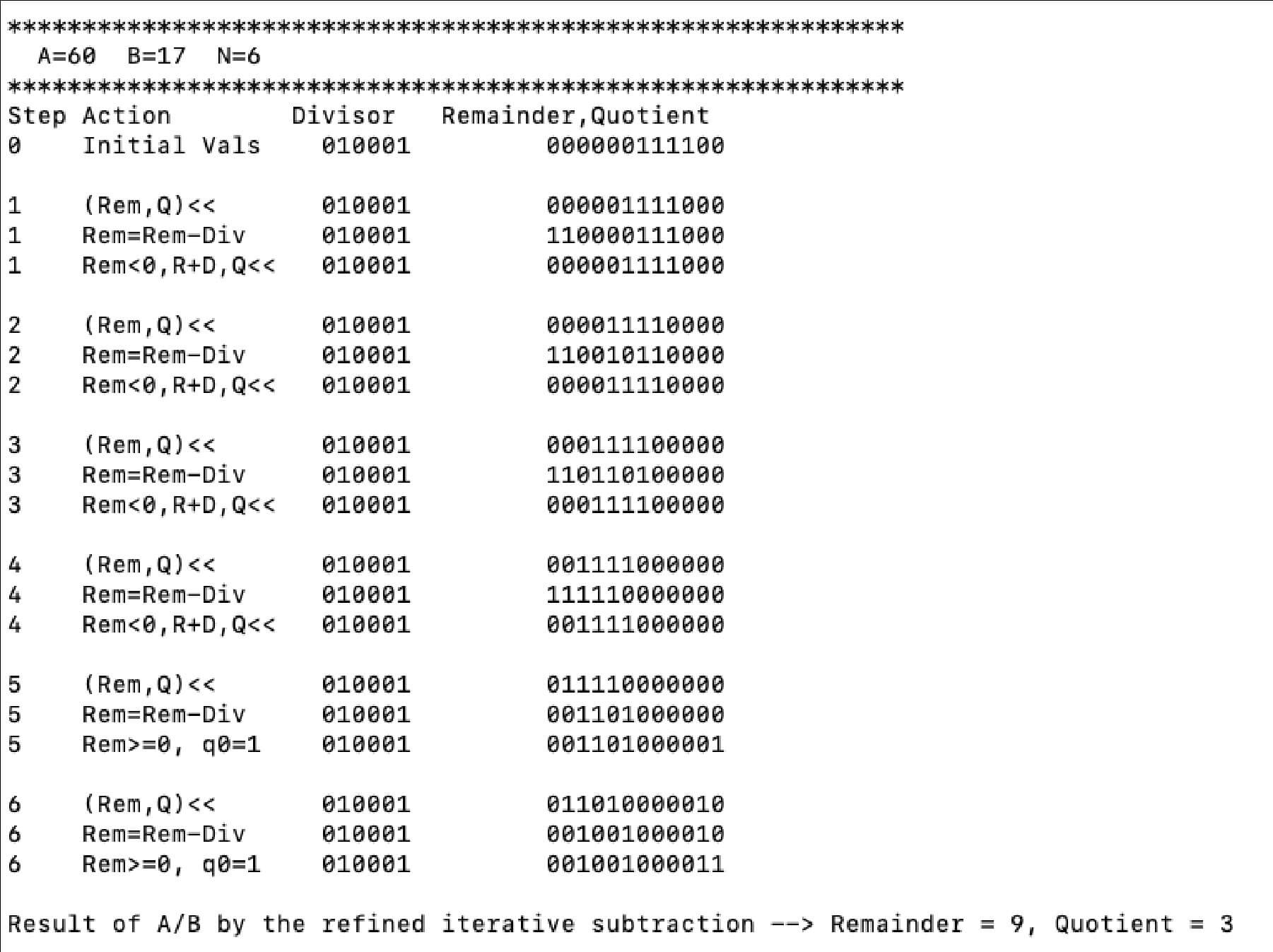
Similar to the previous work, write a program, named ex.3.19.asm to simulate the improved version the division hardware as described in Figure 3.11. Your program should show the contents of each registers and their operations at each step similar to the example below, where the dividend is 1111002 (6010) and divisor is 0100012 (1710). Again, your program must display numbers with exactly n bits. You could lose 5pt if your program cannot work for different value of n.
Note that this algorithm requires a slightly different approach than that shown in Figure 3.9. You will want to think hard about this,
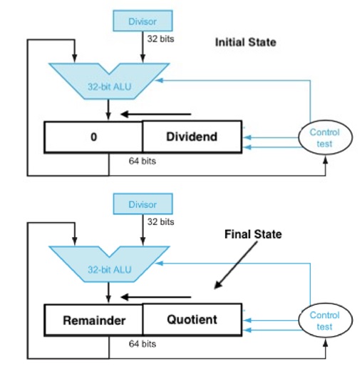
FIGURE 3.11 An improved version of the division hardware. The Divisor register, ALU, and Quotient register are all 32 bits wide, with only the Remainder register left at 64 bits. Compared to Figure 3.8, the ALU and Divisor registers are halved and the remainder is shifted left. This version also combines the Quotient register with the right half of the Remainder register. (As in Figure 3.5, the Remainder register should really be 65 bits to make sure the carry out of the adder is not lost.)
MIPS Project Answer
Multiplication
Start with long-multiplication approach
Starter Code
{`
ex.3.12:
    sw    $ra,  ($sp)
    addi  $sp,  $sp,  4
    move  $t0,  $a0    #  A = multiplicand
    move  $t1,  $a1    #  B = multiplier
    move $t7,   $a2    #  N = number of bits for display, assume N <= 16
    li    $t6,  0
loop:
    beq   $t7, $0,  done    #  if $t1==0 quit loop
    andi  $t4, $t1, 1       #  t4  = right most bit of multiplier t1.
    beq   $t4, 0,   ZERO    #  if t4 == 0, then jump to ZERO
ONE:
    addu  $t6, $t6, $t0     #  otherwise, t1 is one, so we do t6 += t0 (multiplicand)
ZERO :
    sll   $t0, $t0,   1     #  shift t0 (multiplicand) 1 bit to the left
    srl   $t1, $t1,   1     #  shift t1 (multiplier) 1 bit to the right
    addi  $t7, $t7    -1
    j     loop`}
Optimized Multiplier
Perform steps in parallel: add/shift
Product is 64-bit long, stored in two registers
Starter Code
{`
ex.3.13:
    sw      	$ra,  ($sp)
    addi    	$sp,  $sp,  4
    move    $t0,  $a0         # t0 = multiplicand
    move    $t6,  $a1         # t6 = multiplier.
    move    $t7, $a2          # number of bits,
    move    $t1, $a2          # loop count
loop:
    beq   	$t1, $0,  done    #  if $t1==0 quit loop
    addi  	$t1, $t1, -1      #   t1 --;
    andi  	$t4, $t6, 1       #  t4  = right most bit of multiplier t6.
    beq   	$t4, 0,   ZERO    #  if t4 == 0, jump to ZERO
ONE:
    sllv  	$t5, $t0, $t7
    addu  	$t6, $t6, $t5     #
ZERO :
    srl   	$t6, $t6, 1       #  shift t6 1 bit to the right
    j     	loop`}
Print Rightmost N Bits
{`display.bits:     	# display the rightmost n bits of the number x in a0,
#where n is specified in $a2
    	li    	$t2,    32
    	sub  	 $t2,    $t2,    $a2       	# t2 = 32 - n
    	sllv 	 $t3,    $a0,    $t2       	# t3 = x << (32-n)
    	move  	$t2,    $a2               	# t2 = n
L1:	move  	$a0,    $t3               	#   a0 = t3
    	srl   	$a0,    $t3,    31        	#   a0 = t3 >> 31
   	 li   	 $v0,      1           	#   print MSB as an integer
    	syscall
   	 sll   	$t3,    $t3,    1         	#   t3 = x << 1
    	addi  	$t2,    $t2,    -1        	#   n--
    	beq   	$t2,    $0,     return    	#
    	j     	L1`}
Print Rightmost 6 Bits of a Number
{`
# print the right most 6 bits of integer x in 32-bit register $t0 (001010)
00000000 00000000 00000000 00001010 # t0 = 0010
00101000 00000000 00000000 00000000 # t1 = t0 << 26 (32-6)
00000000 00000000 00000000 00000000 # t2 = t1 >> 31, (MSB of t0)
print t2 # print 0 (MSB of x)
01010000 00000000 00000000 00000000 # t1 = t1 << 1
00000000 00000000 00000000 00000000 # t2 = t1 >> 31, (2nd MSB of t0)
print t2 # print 0 (2nd MSB of x)
10100000 00000000 00000000 00000000 # t1 = t1 << 1
00000000 00000000 00000000 00000001 # t2 = t1 >> 31, (3rd MSB of t0)
print t2 # print 1 (3rd MSB of x)
01000000 00000000 00000000 00000000 # t1 = t1 << 1
00000000 00000000 00000000 00000001 # t2 = t1 >> 31, (4th MSB of t0)
print t2 # 0 (4th MSB of t0)
# repeat 2 more times`}
Integer Division Hardware
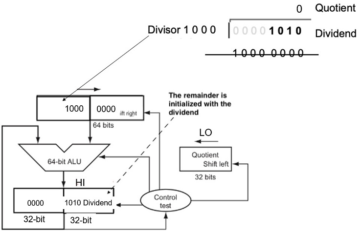
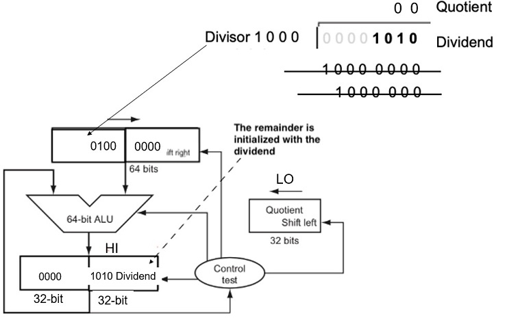
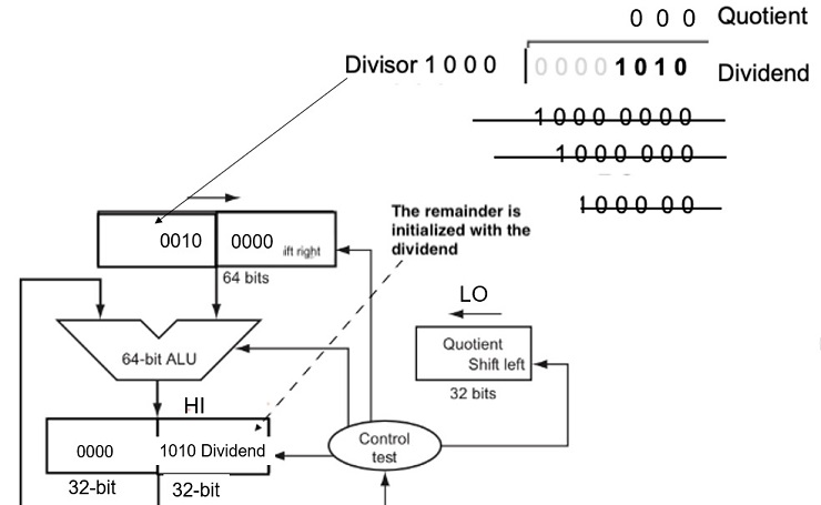
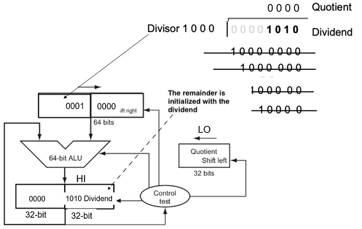
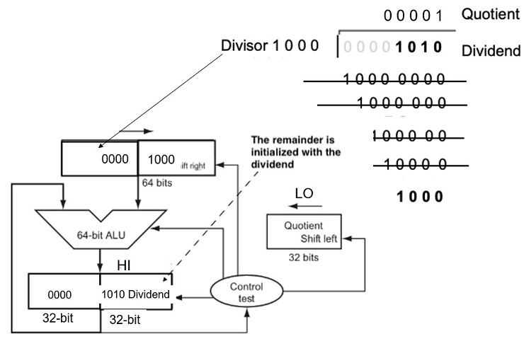
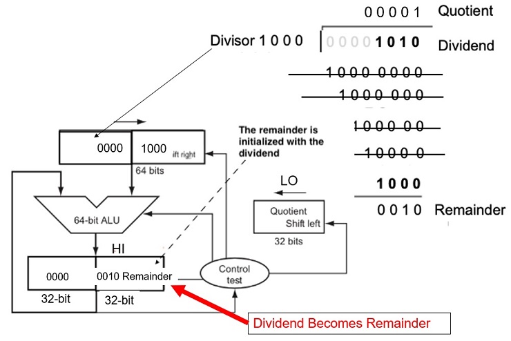
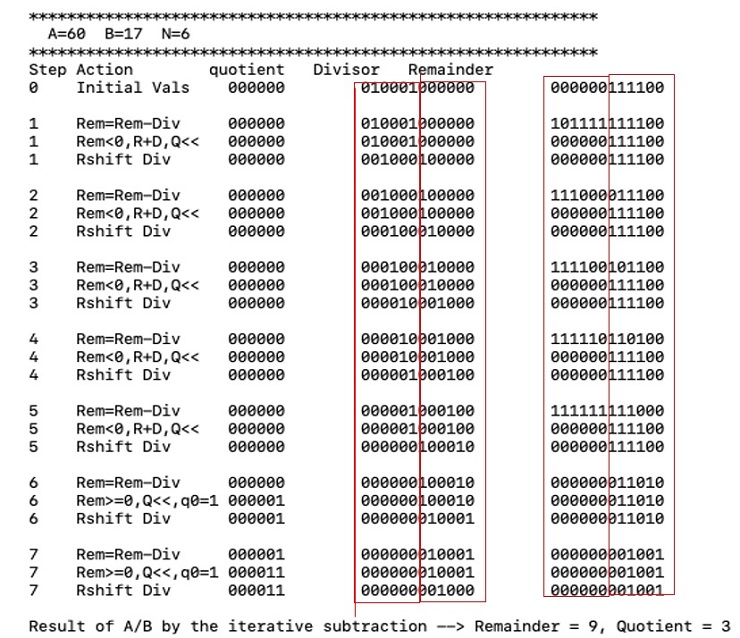
Fig 3.11 An Improved Division Hardware
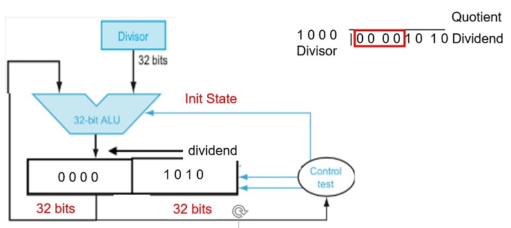
The Divisor register, ALU, and Quotient register are all 32 bits wide, with only the Remainder register left at 64 bits. Compared to Figure 3.8, the ALU and Divisor registers are halved and the remainder is shifted left.