Code Drawing Assignment Help
Code Drawing, Drawing Instruments, Sheet Layout
Introduction to Code Drawing, Drawing Instruments, Sheet Layout, Lettering, Dimensioning etc.
In the 20th century, growing international engineering and technology development, the introduction of foreign evolved technologies, technical collaboration between mutual countries, exchange and export of technologies have necessitated the inter-nationalisation of engineering drawing standards. Many countries now unanimously follow these guidelines. These standards are applicable to the following topics in the field of Architectural drawing:
Drawing sheets: The code specifies the sizes and layout of drawing sheets. Below is a table explaining sheet sizes:
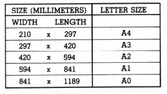
Architecture students generally use A2 or A3 size for their class work.
Code Drawing Assignment Help By Online Tutoring and Guided Sessions from AssignmentHelp.Net
Layout of drawing sheet- After fixing the drawing sheet on the drawing board, draw:
i) Border lines: Perfect rectangular working space is obtained by drawing border lines. A filinf margin of 20 mm (min) width at the left hand edge of the sheet is to be provided. At the top, bottom and the right hand edges, a margin of 5mm (min) may be provided.
ii) Spacing of drawing: when only one figure is to be drawn on a sheet it should be drawn in the centre of the working space. For more than one figure, the space should be planned and divided into suitable blocks.
iii) Title Block: An additional margin of 65mm width is drawn at the bottom of the sheet called the TITLE BLOCK, to furnish the details, namely, name of the institution, name of the student, class, roll number, title of the drawing, date of submission etc.
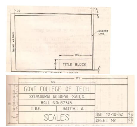
Drawing Instruments: The drawing instruments, which make it possible to work accurately with the scale, are as follow:
Pencil
The pencil is a draftsmans most useful instrument. The selection of the pencil for the work and a sharpening of it carefully to a long tapering point is very important for the draftsman. For sketching, use a drawing pencil of grade F: for average work and lettering, use and FB or H, and for very accurate work, where fine, sharp lines are necessary, a 2H or 4H. See figure;
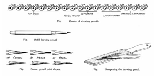
Drawing Board
This should be a perfectly smooth flat board of soft wood are made in such a way that it cannot warp or split. All angles should be perfectly true and smooth. See figure

T. Square
The T. square is used for ruling horizontal lines only. See figure
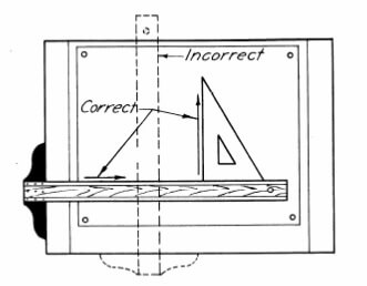
Triangles
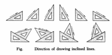
Two triangles will be needed, a 45 degree triangle and 30 degree 60 degree triangle.
French Curved
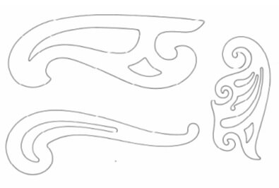
An irregular or French curve is needed for ruling curved lines other than circle arcs.
Scale
The architectural draftsmans scale is made in various lengths, but a 12-inch triangular scale will be found best for student use. This has on one face the normal full size divisions of the foot. The scales on the other faces of the stick are as follows:
1=1, 1/8=10, 3/8=10, 1/4"=10, 3/16=10, 1/8=10, 3/32=10 The scale at which the drawing is to be made may depend upon three things: first, the size of the paper on which the draftsman wishes to work; second the size of the building or detail to be drawn; third, the amount of detail that is desirable to show in the drawing.

Dividers
These are used to step off equal distances or to divide a line or space into equal parts.
Compasses
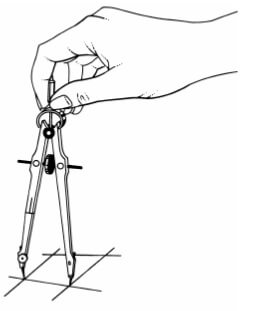
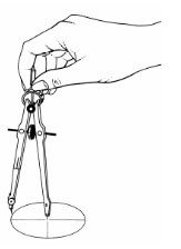
The compasses are used to draw circles and circles arcs.
Ruling Pen
Ruling pen is used for ruling lines in ink.
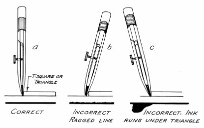
Erasers
Erasers are used for cleaning off light lines or soiled places.
Paper
Detail paper is used for the drawing of building details. It may be had in sheets or in rolls. The rolls vary in width from 36 to 54 inches and contain a from 10 to 50 yards. A 36 inch roll may be cut without waste into sheets 36 by 26, 26 by 18, 18 by 13, 13 by 9 by 6 1/2 inches. Tracing paper is a thin white transparent paper for general use where one drawing is to be made over another.
Water colour paper
Water-colour papers are used for rendered drawings.
Ink
Drawing ink is a heavy India ink especially prepared for this work.
Lettering: Writing of titles, sub titles, dimensions, scale and other details on a drawing board is called lettering. The ability to letter freehand with speed, neatness, beauty of form, uniformity and legibility is a skill very much desired and cherished by all architects. Use of instruments for lettering consumes more time.
The main requirements of lettering, namely, types and sizes of letters and technique of lettering are specified in the IS code. The essential features of lettering on drawings are-
- Legibility
- Uniformity
- Suitability for micro filming and other photographic reproduction
Ratio of height to width, for most of the letters is approximately 5:3. However for M and W, the ratio is approximately 5:4.
Dimensioning: An architectural drawing should contain the details regarding the sizes, besides giving the shape of an object. The expression of details in terms of numerical values regarding distances between surfaces etc., on a drawing by the use of lines, symbols and units is known as dimensioning. General principles followed are:
- All dimension should be detailed on the drawing.
- No single dimension should be repeated except where unavoidable.
- Mark the dimension outside the drawing as far as possible.
- The longer dimensions should be placed outside all intermediate dimensions, so that dimension lines will not cross extension lines.
Methods of dimensioning:
Unidirectional system: In this method dimensions shall be horizontally placed so that they can be read from the bottom of the drawing sheet. Here the dimension lines may be interrupted preferably near the middle for the insertion of dimensions.

Aligned system: In aligned system, dimensions shall be placed parallel (aligned) to and above the dimension lines, preferably in the middle and not by interrupting the dimension lines. Here the dimensions can be read from the bottom or from the right side of the drawing.

All dimensions in one particular drawing should be expressed in one unit only. Angular dimensions are marked in the same manner as the linear dimensions. Dimension lines are terminated by carefully drawn arrowheads. The arrowhead may be open, closed or closed and filled in. when enough space is not available, arrowheads should be placed outside. Instead of arrowheads, the ends of the dimension lines maybe marked by oblique stroke drawn as a short line drawn at 45 degrees as shown.


