The J-K Flip Flop Assignment Help
Objectives:
1. to investigate the operation of J-K flip-flops
2. to appreciate the need for switch debouncing
3. to build and analyse the operation of an asynchronous counter
4. to modify the counter so that it will both count up and count down
5. to design and simulate a three digit decade counter.
Experimental Work


The truth table of
1. Construct the following circuit on the Logic Tutor, monitoring the clock, Q and QBAR outputs with the on-board LEDs.
2. Complete Table 1, entering an X for ‘don’t care states’.
| Table 1 | INPUTS | OUTPUTS | ||||
| Preset(S) | Clear(R) | Clock | J | K | Q | QBAR |
| 0 | 1 | |||||
| 1 | 0 | |||||
| 0 | 0 | |||||
|
| 1 | L | L | |||
|
| 1 | H | L | |||
|
| 1 | L | H | |||
| 1 | H | H | ||||
![]()
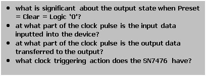
3. Your observations should enable you to answer the following questions:
Simulation- Frequency division properties of J-K Flip-Flops
1. Replace the existing clock circuit with the TTL output of the signal generator.
2. Set the generator to 1 kHz. and Preset = Clear = J = K= ’1’
4. Connect the oscilloscope to both the clock input and Q output and sketch the two observed waveforms above each other on the same time axis.
5. What is the ratio of the output to the input frequency?
Assignment Help | Electrical Assignment Help | Online Tutoring | Sample Homework


