Shift Registers Digital Lab Help

Objectives:
To construct shift registers using D-type and J-K Flip-flops and to investigate their properties.
To investigate the properties of the 74194 universal shift register.
Simulation Work
Serial Load Shift Register using D-type Flip-Flops.
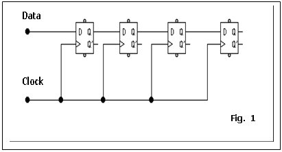 Enter the following circuit (Fig. 1) into Electronics Workbench, adding any necessary components to enable the flip-flops to be:
clocked high and low
cleared.
input ‘0’ and ‘1’ data
observe the Q outputs on LEDs
- Clear the registers by momentarily taking the clear input low.
- Set the clock to logic ‘0’ and
the Data input to logic ‘1’. Set the clock to logic ‘1’ and note the state of the Q outputs.
- Return the Data input to logic ‘0’ and repeatedly take the clock high and low, noting the state of the outputs for each clock pulse. Complete the following table and explain what is happening in the circuit.
| Clock Pulse | Data | QA | QB | QC | QD |
| 0 | 0 | 0 | 0 | 0 | 0 |
| 0 | 1 | 0 | 0 | 0 | 0 |
| 1 | 0 | ||||
| 2 | 0 | ||||
| 3 | 0 | ||||
| 4 | 0 | ||||
| 5 | 0 |
Assignment Help | Physics Assignment Help | Physics Homework Help | Physics project Help | Online Tutoring | Sample Homework


