Schmitt Trigger Simulation
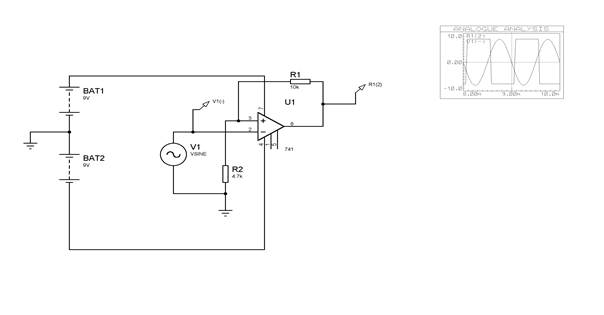
Examine the circuit of figure below
A note on the Schmitt Trigger
You will notice that unlike all other amplifier circuits you have met so far, this amplifier has the feedback network connected to the non-inverting input.

Suppose the output of the amplifier is saturated high with an output voltage of Vh, then the non-inverting input will see a voltage of Vh*(R2/(R1+R2). When the signal on the inverting-input exceeds this voltage the output will swing to its saturated low value of -VL which in turn sets up a new voltage on the non-inverting input of :
-VL*(R2/(R1+R2)). The output will remain low until the signal on the inverting-input reaches (and goes lower than) this new voltage when the output will swing back high once more.
We therefore have a system involving two threshold levels of Va=Vh*(R2/(R1+R2)) and Vb= -VL*(R2/(R1+R2)).
This gives rise to hysterisis (i.e. the signal has to move a distance of Va - Vb) to change the state of the output. It is this hysterisis behaviour that is called a Schmitt trigger. A device with this characteristic is useful to eliminate the effect of noise on a signal. A signal can suffer noise degradation with unwanted swings up to Va above zero and Vb below zero without affecting the switching function.
Try simulating the circuit of figure 2 where R2 = 4.7k and R1 = 10k and apply a sine generator to the input of frequency 1kHz and amplitude 8V.
Examine V out high and V out low from the Op Amp and evaluate the switching points Va and Vb. Do they comply with the expected values?
Assignment Help | Physics Assignment Help | Physics Homework Help | Physics Project Help | Online Tutoring | Sample Homework


