How To Simulate Using The ISIS Program
Select the components from the right hand window and place them onto the drawing area and then connect them up (fig 3). The mouse turns to a cross at a component node. Just click (release) move to another node, then click (release) to wire two nodes together. Fig 3 highlights the rotation arrow - needed for correct component orientation. Keys F5 - F11 are the zoom keys. The window at the top right is an overview of the drawing: use this to place the view window over the area you are editing.

To move a component’s position, just right click to highlight it, then click left - hold drag and release. If you right click twice the component will be removed. Use the U key to undo an operation.
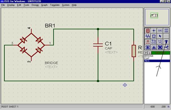
Fig 3
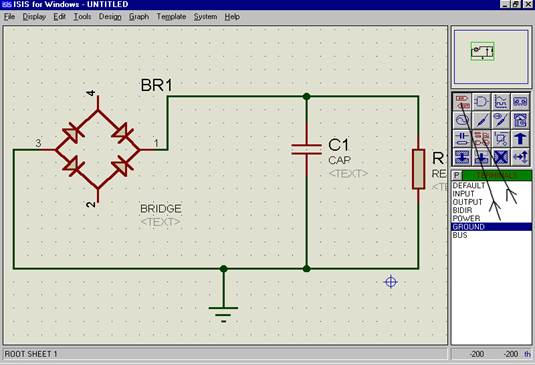
Step 5
Now add a ground connection. This can be found using Gadgets Mode” and “Terminal” (see fig 4).
How To Simulate Using The ISIS Program Assignment Help | Online Tutoring | Sample Homework


