Flip flops Assignment Help
Flip flops Assignment Help
www.assignmenthelp.net is an online tutoring website designed to provide tutoring help to college and school level students. Electrical engineering students can get help with Flip flops assignments, electrical engineering homework help or electrical engineering Assignment Help. Submit Your Courseworks and get 100% plagiarism free solutions. Call us, email us or chat with us. We are available 24*7 for your assistance. Take use of our services to get good grades in your academics.
Flip flops Tutor
We have highly professional tutors and an excellent team for teaching Flip flops and its problems. Tutors for this topic are electrical engineers with masters and PHD degrees. They use latest advanced technologies to teach different difficult concepts to students. Tutors use such teaching methodologies so that students gain maximum interest in the subject.

Flip flops
Flip flop or latch is a circuit which has two stable state and is used to store the state information. Flip flop is the basic storage element in sequential logic. The circuit’s state can be changed by applying signals to one or more control inputs and we get one or more outputs. A flip flop is a bistable multivibrator. Flip-flops and latches are used in communications, computers and many other systems. They are the fundamental building block of digital electronics systems. Latches and flip flops are used as data storage elements. Sequential logic is the circuit in which such storage can be used for storage of state. Flip flops or latches are used in finite state machine. In a finite state machine, the output and next state depend on its current input and its current state (hence, previous inputs). It can also be used for counting of pulses and for synchronizing variably-timed input signals to some reference timing signal. Flip flops are basically of two types: clocked (synchronous or edge-triggered) or simple (transparent or opaque); the simple ones are commonly called latches. Latch is mainly used for storage elements, while clocked devices are described as flip-flops. A latch is level-sensitive, whereas a flip-flop is edge-sensitive. That is, when a latch is enabled it becomes transparent, while a flip flop's output only changes on a single type (positive going or negative going) of clock edge.
Flip flops Assignment Help By Online Tutoring and Guided Sessions from AssignmentHelp.Net
The most common types of flip flops are described below:
1. SR latch
Here S and R stand for set, reset respectively. The most basic latch is the basic SR latch when we use static gates as building blocks. The output Q represents the stored bit. We can make SR latch from a pair of cross coupled NOR logic gates. While the S and R inputs are both low, feedback maintains the Q and Q’ outputs in a constant state, with Q’ the complement of Q. If S (Set) is pulsed high while R (Reset) is held low, then the Q output is forced high and stays high when S returns to low; similarly, if R is pulsed high while S is held low, then the Q output is forced low and stays low when R returns to low.
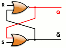
Fig (1): An SR latch, constructed from a pair of cross-coupled NOR gates.
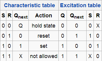
Fig (2): SR Latch Operation
When R = S = 1, then both the NOR gates output zeros thereby breaking the logical equation Q = Q’. Hence this combination, R = S = 1 is also called forbidden state or restricted state. The combination is inappropriate in circuits where both inputs may go low simultaneously (i.e. a transition from restricted to keep). The output will lock at either 1 or 0 depending on the propagation time relations between the gates (a race condition).
2. D Flip flop
The D flip-flop captures the value of the D-input at a definite portion of the clock cycle (such as the rising edge of the clock).This captured value becomes the Q output and at other times Q- the output does not change. The D flip flop can be viewed as a zero order hold, a memory cell or a delay line. D flip flop is also known as “delay” or “data” flip flop. It is widely used.

Fig (3): D Flip flop symbol.
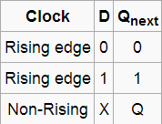
Fig (4): D Flip flop Truth Table.
Note: Here,'X' denotes a Don't care condition, meaning the signal is irrelevant.
Most D-type flip-flops in ICs have the capability to be forced to the set or reset state (which ignores the D and clock inputs), much like an SR flip-flop. Usually, the illegal S = R = 1 condition is resolved in D-type flip-flops. By setting S = R = 0, the flip-flop can be used as described above. Here is the truth table for the others S and R possible configurations:
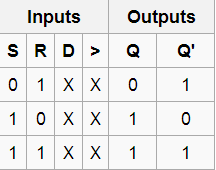
Fig (5): D flip flop Truth table for the others S and R possible configurations.
3. T Flip flop
T flip flop toggles (changes state) whenever the input clock is strobed provided the T input is high. The flip flop holds the previous value if T input is low. We have a characteristic equation (written below) describing such behaviour:
![]()
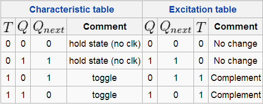
Fig (6): T Flip flop truth table

Fig (7): Circuit symbol for T flip flop.
The T flip flop has a “divide by” feature which means that if T is high then T flip flop divides the clock frequency by two. It means that if clock frequency is 6 MHz then the output frequency obtained from the flip flop will be 3 MHz. Such feature finds application in various kinds of digital counters. A T flip flop can also be built using a D flip flop (T input and Qprevious is connected to the D input through an XOR gate) or JK flip flop (J & K pins are connected together and act as T).
4. JK Flip flop
JK Flip flop enhances the behaviour of the SR flip flop (J=Set, K=Reset) as it interprets the S = R = 1 condition as a "flip" or toggle command. The combination J = 1, K = 0 is a command to set the flip-flop; the combination J = 0, K = 1 is a command to reset the flip-flop; and the combination J = K = 1 is a command to toggle the flip-flop, i.e., change its output to the logical complement of its current value. Setting J = K = 0 does NOT result in a D flip-flop, but rather, will hold the current state. To synthesize a D flip-flop, simply set K equal to the complement of J. Similarly, to synthesize a T flip-flop, set K equal to J. The JK flip-flop is therefore a universal flip-flop, because it can be configured to work as an SR flip-flop, a D flip-flop, or a T flip-flop.
The characteristic equation of the JK flip-flop is:
![]()
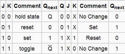
Fig (8): JK Flip flop Truth table.

Fig (9): JK Flip flop circuit symbol.

Fig (10): JK Flip flop Timing Diagram.
Flip flops | Flip flops Assignment Help | Electrical engineering homework help | Electrical engineering Assignment Help | Electrical engineering project help | help with Electrical Engineering Courses


