Counters Assignment Help
Counters Assignment Help
Contact us to get any help related to assignments, homework, projects, dissertation or any other online tutoring help. www.assignmenthelp.net provides online tutoring help to school and college level students. Contact us through chat, email or phone; we are available 24*7. We provide 100% plagiarism free service.
Counters Tutor
We have highly professional tutors and an excellent team for teaching counters and its problems. Tutors for this topic are electrical engineers with masters and PHD degrees. They use latest advanced technologies to teach different difficult concepts to students. Tutors use such teaching methodologies so that students gain maximum interest in the subject.

Counters
In digital electronics a counter is a device which displays and stores the number of time a particular process or event has occurred, generally with respect to a clock signal. Counters can be implemented very easily by using register type circuits like flip flop. There are many different kinds of counters, some of them are mentioned below:
Ripple counter/ Asynchronous counter- the changing state bit is the clock, the clock is used for the subsequent state flip flop.
Synchronous counter – a single clock controls and changes all state bits.
Decade counter – per stage counts through 10 states.
Up/down counter – control input commands both up counting and down counting.
Ring counter – formed by a shift register with feedback connection in a ring.
Johnson counter – a twisted ring counter.
Cascaded counter.
modulus counter.
Counters Assignment Help Through Online Tutoring and Guided Sessions from AssignmentHelp.Net
Asynchronous counters
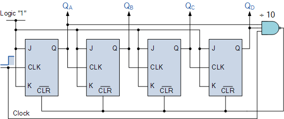
Fig (1): Asynchronous decade counter.
Starting from 0 (“0000”) up till the counter reaches 10 (1010), the asynchronous counter counts upwards on each leading edge of the input clock signal. The outputs QA and QD now equals logic “1” and output from NAND gate changes state from logic "1" to a logic "0" level and whose output is also connected to the CLEAR ( CLR ) inputs of all the J-K Flip-flops. Due to this signal, on the count of 10 all the Q outputs reset back to binary 0 (0000). Once QA and QD are both equal to logic "0" the output of the NAND gate returns back to a logic level "1" and the counter restarts again from "0000". We now have a decade or Modulo-10 counter.
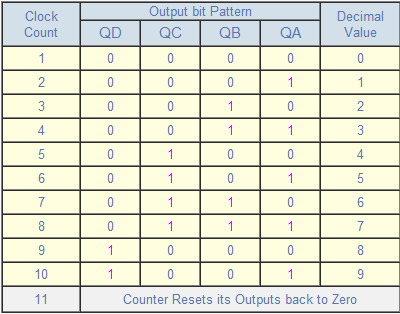
Fig (2): Truth table for asynchronous decade counter.
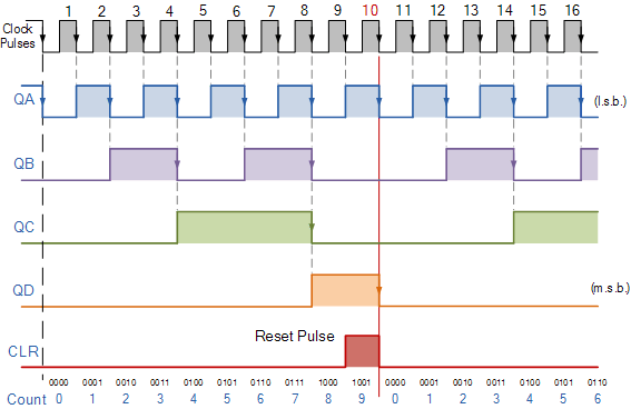
Fig (3): Asynchronous decade counter timing diagram.
Synchronous counters
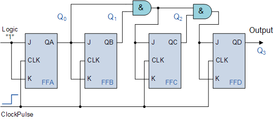
Fig (4): 4 bit Synchronous counter.
We can see that the clock pulses are given directly to each JK Flip flop and both J and K inputs are all tied together in toggle mode. But we can see that in the first flip flop, which is the least significant bit, the J and K inputs are connected as ‘1’, which makes the flip flop to toggle on every clock pulse. Then the synchronous counter follows a predetermined sequence of states in response to the common clock signal, advancing one state for each pulse.
The output Q of flip flop A is connected to the J,K inputs of the flip flop B whereas the J, K inputs of flip flops C, D are driven from AND gates. Output and input of the previous stage supply signals to the AND gate. If we enable each J-K flip-flop to toggle based on whether or not all preceding flip-flop outputs (Q) are "HIGH" we can obtain the same counting sequence as with the asynchronous circuit but without the ripple effect, since each flip-flop in this circuit will be clocked at exactly the same time. There is no propagation delay in synchronous counters as all the counter stages are triggered in parallel. The maximum operating frequency of this type of counter is much higher than that of a similar asynchronous counter.
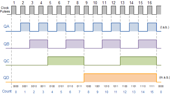
This 4-bit synchronous counter counts sequentially on every clock pulse and the resulting outputs count upwards from 0 ( "0000" ) to 15 ( "1111" ). Hence, this counter is known as 4-bit Synchronous Up Counter. Synchronous counters are formed by connecting flip flops together and any number of flip flops can be connected together to form a “divide by n” binary counter. The modulo's or "MOD" number still applies as it does for asynchronous counters so a Decade counter or BCD counter with counts from 0 to (2^n)-1 can be built along with truncated sequences.
Ring counter
A ring counter is a circular shift register in which only one of the flip flop is in state ‘1’ rest others are in ‘0’ state. A ring counter is a cascade connection of flip flops in style of a ring, that is, with the output of last one connected to the input of the first. A pattern consisting of a single bit is circulated so the state repeats every n clock cycles if n flip-flops are used. It can be used as a cycle counter of n states.
Johnson counter
Johnson counter is a counter in which the output from the last stage is first inverted and then fed as an input to the first stage. Johnson counter is a form of modified ring counter. This can be easily implemented using D- or JK-type flip-flops. The register cycles through a sequence of bit-patterns, whose length is equal to twice the length of the shift register, continuing indefinitely. They are used in very specialist applications, including those similar to the decade counter, digital-to-analog conversion, etc.
Counters | Counters Assignment Help | Electrical engineering homework help | Electrical engineering Assignment Help| Electrical engineering project help| help with Electrical Engineering Courses.


