Rational Rose Assignment Help
ROSE = Rational Object Oriented Software Engineering
A set of visual modeling tools for development of object oriented software is Rational Rose.

Visual Modeling is the process of graphical representation of picture or sculpture for the system to be developed :
- Presenting essential details
- Filtering out non-essential details
- Viewing the system from different perspectives
Rational Rose is a type of tool set produced and marketed by Rational Software Corporation. Rational Rose is commercial case-tool software. Rational Rose is an operational tool set and it is used for the Unified Modeling Language (UML). In UML there are different types of notations, allowing the specification of the artifacts of design from many different perspectives and for different objectives during the computer engineering life cycle. Most of the notations are directly supported through the Rose tool set.
It supports two essential elements of modern software engineering:component based development and controlled iterative development. Models created with Rational Rose can be visualized with several UML diagrams.
Rational Rose Views Related to the Software Development Life Cycle.
Rational Rose models have these four views:
- Use Case View
- Logical View
- Component View
- Deployment View
Rational Rose Assignment Help By Online Tutoring and Guided Sessions from AssignmentHelp.Net

The Use Case View
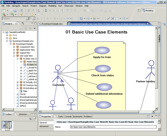
The use-case view helps you to understand and use the system. This view shows us how actors and use cases interact.
The diagrams in this view are:
- Use-case diagrams
- Sequence diagrams
- Collaboration diagrams
- Activity diagrams
This view contains a Main diagram by default. Additional diagrams can be added throughout the analysis and design process.
The Diagram given below shows the Use Case View of Rational Rose

The Logical View
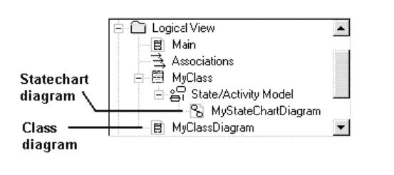
- The logical view addresses the functional requirements of the system.
- This view looks at classes and their relationships.
- The diagrams in this view are:
- Class diagrams
- State chart diagrams
The Diagram given below shows the Logical View of Rational Rose

The Component View
- The component view addresses the software organization of the system.
- This view contains information about the software, executable and library components for the system.
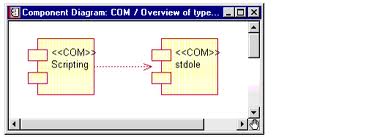
- This view contains only component diagrams.
- The component view contains a Main diagram by default. Additional diagrams can be added to this view throughout the analysis and design process.
The Diagram given below shows the Component View of Rational Rose

The Deployment View
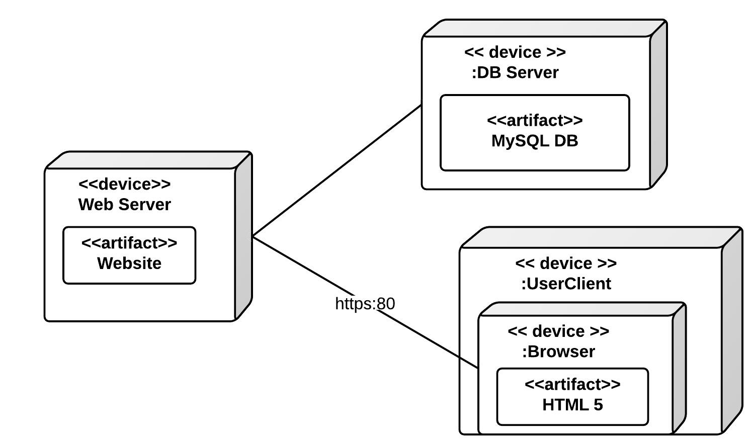
- The deployment view shows the mapping of processes to hardware.
- This type of diagram is most useful in a distributed architecture environment where you might have applications and servers at different locations.
- This view contains only one diagram the deployment diagram.
The Diagram given below shows the Deployment View of Rational Rose

Steps For Starting Rational Rose
Start Rose
- Start → Programs → Rational Rose Introduction to Rational Rose 45
Create a New Model
When Rose is started
When Rose has been
- Started: File → New
From Scratch: New
From File System:
Existing OR Recent
To Save a Model
- File → Save or Save As
Delete an Element
- Shallow Delete
- Edit Delete
- Select element in diagram → key DEL
- It is not deleted from the MODEL!! (Only from the diagram, not from Browser)
- Deep Delete
- Select element in Browser → click right button → Delete
- Select element in diagram → Click CTRL+D
- It is deleted from the MODEL!! (It will disappear from the diagram and from the Browser Move Elements across Packages
To submit Rational Rose assignment Click here
