Wien Bridge Oscillator In Analog
Simulation Circuit
Figure 20 shows the diagram of a Wien Bridge oscillator using a LM741 operational amplifier running from +/- 9V.
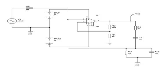

Figure 20
R1 = R2 = R = 10k
C1 = C2 = C = 10nF
R3=20.5k, R4=10k, R5=1M
The frequency of oscillation is given by 1/(2'RC). With the values shown what is the frequency?
To ensure oscillation, the amplifier gain must be 3 so R3 = 2.R4.
Due to the nature of simulation, the circuit finds a solution where the output is zero. It is necessary to introduce a small disturbance into the circuit and also increase the gain of the amplifier slightly.
With R4 = 10k, R3 has been set to 20.5k.
To disturb the circuit a sine generator has been connected via a 1M resistor to the amplifier input. The generator has been set to an amplitude of 1mV. The frequency of the generator is not critical, (in the above simulation it was set to 1kHz).
Run the simulation and check that the frequency is near that expected.
You may need to run the simulation for ten’s of ms before the circuit stabilises. Try setting the start time to 200ms and the stop time to 210 ms. Examine the start up transient at an earlier time.
Set R to half its value (R1 = R2 = 5k) and re-run the simulation. If the simulation does not run properly then increase the value of the gain setting feedback resistor (R3) to 22k.
Run the simulation from various starting times. Examine the start up transient. Is the frequency near the expected value?
Assignment Help | Physics Assignment Help | Physics Homework Help | Physics Project Help | Online Tutoring | Sample Homework


